Kubernetes Architecture Explained
A detailed walkthrough of Kubernetes cluster architecture, from the control plane components that manage state to the worker node agents that run your containers and the networking model that connects them.
Cluster architecture: the split between control plane and data plane
Kubernetes architecture explained at its core is a separation between the control plane (the brain) and the data plane (the muscles). The control plane decides what should run, where it should run, and what to do when something fails. The data plane actually runs the containers and routes the network traffic. This separation is what makes Kubernetes scalable: you can add hundreds of worker nodes without changing the control plane architecture. A Kubernetes cluster is a set of machines called nodes. At least one node runs the control plane components. The remaining nodes are worker nodes that run application workloads. In managed Kubernetes services like EKS, AKS, and GKE, the cloud provider operates the control plane and you never see the underlying machines. In self-managed clusters (kubeadm, k3s, Rancher), you're responsible for control plane availability, which typically means running three control plane nodes behind a load balancer for etcd quorum. The declarative model is the fundamental design principle. You submit a desired state to the API server: 'run three replicas of this container image with 512MB memory and a persistent volume.' The control plane continuously compares the desired state to the actual state and takes corrective action. If a pod crashes, the controller creates a replacement. If a node goes offline, the scheduler places the affected pods on healthy nodes. This reconciliation loop runs every 10 seconds by default and is the reason Kubernetes self-heals. Everything in Kubernetes is an API resource stored in etcd. Pods, Services, Deployments, ConfigMaps, Secrets, and Custom Resource Definitions (CRDs) all follow the same pattern: a metadata section with name and labels, a spec section with desired state, and a status section updated by controllers.
Control plane deep dive: apiserver, etcd, scheduler, controller-manager
The kube-apiserver is the front door to the cluster. Every interaction with Kubernetes goes through the API server: kubectl commands, controller reconciliation loops, kubelet status reports, and CI/CD deployments. It validates and processes RESTful requests, authenticates callers via certificates or tokens, authorizes actions via RBAC policies, and persists the resulting state to etcd. In production, the API server runs behind a load balancer on three control plane nodes. It's stateless, so horizontal scaling is straightforward. etcd is the distributed key-value store that holds all cluster state. Every resource you create, every status update from a kubelet, and every leader election result is stored in etcd. It uses the Raft consensus protocol, which requires a majority of nodes (quorum) to accept writes. A three-node etcd cluster tolerates one node failure. A five-node cluster tolerates two. etcd performance directly affects cluster responsiveness. Slow etcd disk I/O (above 10ms fsync latency) causes API server timeouts and delayed scheduling. Use SSDs for etcd storage. Monitor etcd's db_size metric and compact regularly. The kube-scheduler watches for newly created pods with no assigned node and selects a node based on resource requests, affinity rules, taints, and topology constraints. Scheduling is a two-phase process: filtering (eliminate nodes that can't run the pod) and scoring (rank remaining nodes by preference). Custom scheduler profiles let you weight factors differently. For GPU workloads, you might score nodes with available nvidia.com/gpu resources higher. The kube-controller-manager runs the built-in controllers: ReplicaSet controller (maintains pod count), Deployment controller (manages rollouts), Node controller (detects offline nodes), and Job controller (runs pods to completion). Each controller watches specific resource types through the API server and acts when actual state diverges from desired state. The cloud-controller-manager handles provider-specific logic: creating load balancers for Service type LoadBalancer, attaching persistent volumes, and updating node metadata with cloud-specific zone information.
Worker nodes: kubelet, kube-proxy, and container runtime
The kubelet is the agent running on every worker node. It receives pod specifications from the API server, instructs the container runtime to start containers, monitors their health, and reports status back to the control plane. The kubelet runs liveness probes (is the container alive?), readiness probes (can it accept traffic?), and startup probes (has it finished initializing?). A failed liveness probe triggers a container restart. A failed readiness probe removes the pod from Service endpoints, stopping traffic flow to it. Configure probe timeouts and thresholds carefully. A liveness probe with a 1-second timeout on a Java application that takes 30 seconds for a full GC will restart healthy containers. The container runtime executes containers. Kubernetes removed native Docker support in v1.24, standardizing on the Container Runtime Interface (CRI). containerd is the default runtime for EKS, AKS, and most distributions. CRI-O is the default for OpenShift. Both implement the same CRI specification, so your container images work identically regardless of runtime. The runtime pulls images, creates containers, manages their lifecycle, and reports resource usage. For security-sensitive workloads, gVisor (runsc) and Kata Containers provide additional isolation by running containers in lightweight VMs or sandboxed kernels. kube-proxy manages network rules on each node. When you create a Service, kube-proxy configures iptables rules (or IPVS rules in IPVS mode) that route traffic destined for the Service's ClusterIP to one of the backing pods. In iptables mode, kube-proxy creates DNAT rules with probability-based load balancing. IPVS mode uses kernel-level load balancing with round-robin, least-connections, or shortest-expected-delay algorithms, and scales better beyond 1,000 services. The kubelet and kube-proxy together make a node ready to run workloads. The kubelet handles the compute aspect (starting and monitoring containers), and kube-proxy handles the networking aspect (routing traffic to the right containers).
Key workloads: Deployments, StatefulSets, DaemonSets, and Jobs
A Deployment manages stateless application replicas. You specify the container image, resource requests and limits, environment variables, and the number of replicas. The Deployment controller creates a ReplicaSet, which creates the pods. Rolling updates replace pods incrementally: the new ReplicaSet scales up while the old one scales down, controlled by maxSurge (how many extra pods to create) and maxUnavailable (how many pods can be down simultaneously). Set maxUnavailable to 0 and maxSurge to 1 for zero-downtime deployments. Deployments are the right choice for web servers, API services, and stateless workers. A StatefulSet manages pods that need stable identities and persistent storage. Each pod gets a predictable hostname (redis-0, redis-1, redis-2) and a PersistentVolumeClaim that survives pod rescheduling. Pods start and stop in order: redis-0 starts before redis-1, and redis-2 stops before redis-1. This ordering matters for databases and clustered systems. PostgreSQL with Patroni, Kafka brokers, Elasticsearch nodes, and Redis Sentinel clusters all use StatefulSets. The stable hostname lets pods discover each other via DNS (redis-0.redis-headless.default.svc.cluster.local) without a service mesh. A DaemonSet runs exactly one pod on every node (or a subset matching a node selector). Use DaemonSets for node-level concerns: log collection agents (Fluent Bit, Filebeat), monitoring exporters (node-exporter for Prometheus), storage drivers (EBS CSI driver), and network plugins (Calico, Cilium). When a new node joins the cluster, the DaemonSet controller automatically schedules a pod on it. When a node is removed, the pod is garbage-collected. A Job runs a pod to completion and tracks success. Set completions to define how many times the pod should succeed and parallelism to define how many pods run concurrently. CronJobs create Jobs on a cron schedule. Use Jobs for database migrations, batch processing, data exports, and one-time setup tasks. Set activeDeadlineSeconds to prevent runaway jobs from consuming cluster resources indefinitely.
Networking: ClusterIP, NodePort, LoadBalancer, Ingress, and CNI
Kubernetes networking follows three fundamental rules: every pod gets its own IP address, pods on any node can communicate with pods on any other node without NAT, and agents on a node can communicate with all pods on that node. These rules create a flat network that simplifies service discovery but requires a CNI (Container Network Interface) plugin to implement. A ClusterIP Service assigns a virtual IP address accessible only within the cluster. When a pod sends traffic to the ClusterIP, kube-proxy's iptables rules DNAT the packet to one of the backing pod IPs. ClusterIP is the default Service type and is used for internal communication between microservices. A NodePort Service opens a specific port (30000-32767) on every node. Traffic hitting any node's IP on that port routes to the Service's pods. NodePort is rarely used in production because it exposes services on non-standard ports. It's useful for development clusters without a cloud load balancer. A LoadBalancer Service provisions a cloud provider's load balancer (AWS NLB/ALB, Azure Load Balancer, GCP Network LB) and routes external traffic through it to the Service's pods. Each LoadBalancer Service gets its own external IP and cloud load balancer, which adds cost. For 20 services, you'd have 20 load balancers. An Ingress resource solves this by routing HTTP/HTTPS traffic from a single load balancer to multiple Services based on hostname and path rules. An Ingress controller (NGINX, Traefik, AWS ALB Ingress Controller, Istio Gateway) watches Ingress resources and configures the underlying reverse proxy. Route api.example.com to the API Service, app.example.com to the frontend Service, and api.example.com/v2/* to the v2 API Service, all through one load balancer. The CNI plugin implements the pod networking model. Calico uses BGP to distribute routes and supports network policies for pod-level firewall rules. Cilium uses eBPF for high-performance networking with L7 visibility. AWS VPC CNI assigns real VPC IP addresses to pods, enabling direct communication with other AWS services without NAT.
Diagramming Kubernetes clusters: what to show and how
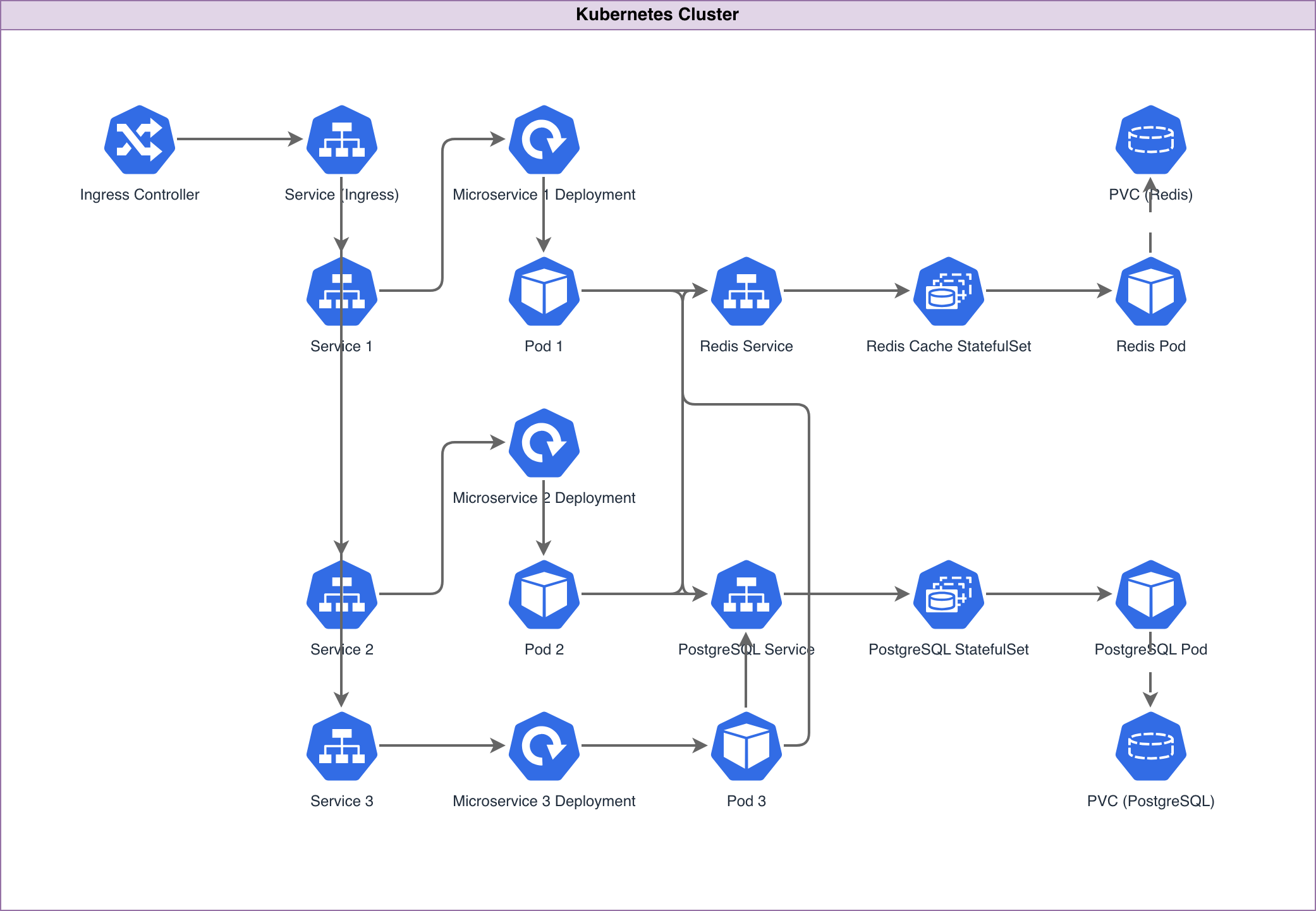
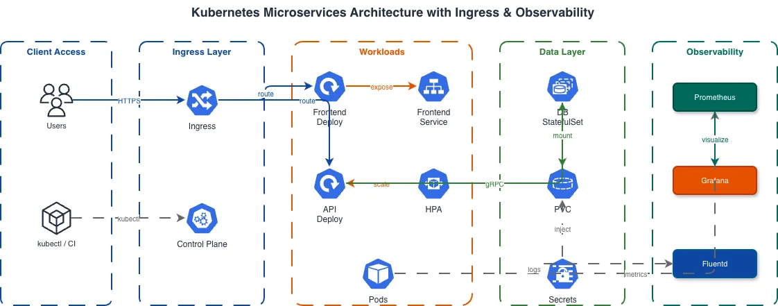
A Kubernetes architecture diagram should show three layers: the control plane, the worker nodes, and the workloads running on them. Draw the control plane as a group containing the API server, etcd cluster, scheduler, and controller-manager. Draw worker nodes as a separate group, with each node containing a kubelet and kube-proxy. Place workload pods inside the worker node group, organized by namespace or application tier. Show the network path from external traffic to your application. Start with the cloud load balancer, connect it to the Ingress controller pod, then to the ClusterIP Services, and finally to the application pods. This path reveals the components involved in every request and helps identify latency bottlenecks. Label each connection: 'HTTPS :443' from the internet to the load balancer, 'HTTP :80' from the load balancer to the Ingress controller, 'HTTP :8080' from the Ingress to the application pod. Show persistent storage connections. Draw PersistentVolumes connecting to StatefulSet pods. Label the storage class (gp3, io2, standard) and capacity. For databases running inside Kubernetes, show the headless Service that provides stable DNS for StatefulSet pods to discover each other. Include the namespace boundaries if your cluster runs multiple applications or environments. Draw a boundary for the 'production' namespace and another for 'monitoring.' This shows isolation and makes it clear which Services are accessible across namespaces and which are not. Diagrams.so generates Kubernetes architecture diagrams from text descriptions. Describe your cluster topology, workload types, and networking configuration, and get a .drawio file with proper Kubernetes icons, node groupings, and network flow paths. The output follows the standard control plane / worker node / workload layering that Kubernetes engineers expect.
Real-world examples

Generate these diagrams with AI
Generate Kubernetes Diagrams from Text with AI
Describe your Kubernetes cluster in plain English. Get a valid Draw.io diagram with CNCF icons, namespace boundaries, deployments, services, and ingress controllers.
Generate Microservices Architecture Diagrams from Text
Describe your service boundaries in plain English. Get a valid Draw.io diagram with API gateways, message brokers, database-per-service patterns, and service mesh routing.
Generate DevOps Diagrams from Text with AI
Describe your DevOps toolchain in plain English. Get a valid Draw.io diagram with correct tool icons, pipeline flows, and infrastructure relationships.