Generate Kubernetes Diagrams from Text with AI
Describe your Kubernetes cluster in plain English. Get a valid Draw.io diagram with CNCF icons, namespace boundaries, deployments, services, and ingress controllers.
This AI Kubernetes diagram generator converts plain-text cluster descriptions into Draw.io diagrams with official CNCF icon sets. Describe a setup like 'production namespace with an nginx ingress controller routing to a frontend deployment (3 replicas) and a backend deployment (5 replicas) with HPA scaling to 20, both connecting to a PostgreSQL StatefulSet with PersistentVolumeClaims.' The AI maps each resource to its CNCF icon, draws namespace boundaries, connects Services to Deployments with labeled selectors, and outputs valid mxGraphModel XML. Architecture warnings flag single-replica deployments (WARN-01) and missing network policies (WARN-04). Every element aligns to a 10px grid. Native .drawio output opens in Draw.io without conversion.
What Is an AI Kubernetes Diagram Generator?
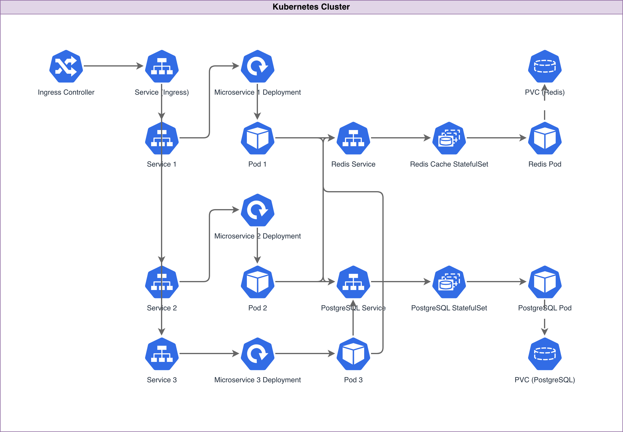
A Kubernetes diagram maps the resources running in a cluster: namespaces, deployments, pods, services, ingress controllers, config maps, secrets, persistent volumes, and the networking between them. Drawing these manually means finding the right Kubernetes icon for each resource type, positioning objects within namespace boundaries, and connecting services to pods with selector labels. An AI Kubernetes diagram generator does all of that from a text prompt. You describe your cluster topology. The AI identifies each Kubernetes resource, assigns the correct CNCF icon (the blue hexagonal Pod icon, the Deployment icon with its replica indicator, the Service icon with its ClusterIP or LoadBalancer type), and arranges resources inside namespace boundaries. Diagrams.so handles Kubernetes-specific layout patterns. Ingress controllers sit at the cluster edge. Services connect to Deployments via label selectors. HorizontalPodAutoscalers attach to their target Deployments with scaling annotations (min: 2, max: 20, target CPU: 70%). PersistentVolumeClaims link to StatefulSets with storage class labels. The AI applies RULE-02 to use official CNCF icons for every resource type, not generic boxes. RULE-06 groups resources by namespace. RULE-05 enforces left-to-right traffic flow from ingress to backend. Architecture warning WARN-01 flags single-replica Deployments with no redundancy. WARN-04 detects missing NetworkPolicy boundaries. WARN-05 identifies ambiguously named resources. VLM visual validation catches overlapping pods and illegible labels. The output is native .drawio XML. Commit it to your GitOps repo alongside your Helm charts and Kustomize overlays.
Key components
- Namespace boundaries as labeled containers grouping all resources within each namespace
- Official CNCF Kubernetes icons for Pods, Deployments, StatefulSets, DaemonSets, Jobs, and CronJobs
- Service resources (ClusterIP, NodePort, LoadBalancer) with port mappings and selector labels
- Ingress controllers (nginx, Traefik, Istio Gateway) with routing rules and TLS termination annotations
- HorizontalPodAutoscaler indicators with min/max replicas and target CPU/memory thresholds
- PersistentVolumeClaim connections to StatefulSets with storage class and capacity labels (e.g., gp3, 100Gi)
- ConfigMap and Secret references shown as dotted lines to consuming Deployments
- Network flow arrows from Ingress through Service to Pod with port numbers (80:8080, 443:8443)
How to generate with AI
- 1
Describe your Kubernetes cluster
Write your cluster topology in plain English with specific resource types and configurations. For example: 'Production namespace: nginx ingress controller with TLS termination. Frontend deployment: 3 replicas of react-app:v2.1 on port 3000, HPA scaling to 10 at 70% CPU. Backend deployment: 5 replicas of api-server:v4.3 on port 8080, HPA scaling to 20 at 60% CPU. PostgreSQL StatefulSet: 3 replicas with 100Gi gp3 PVCs. Redis deployment: 3 replicas for session caching. All inter-service traffic restricted by NetworkPolicies.'
- 2
Select diagram type and provider
Choose 'Kubernetes' as the diagram type and 'Kubernetes' as the cloud provider. Diagrams.so loads the official CNCF icon library with icons for every Kubernetes resource type. Enable opinionated mode to enforce namespace grouping, ingress-to-backend left-to-right flow, and automatic NetworkPolicy boundary visualization.
- 3
Generate and export
Click generate. The AI produces .drawio XML with namespace boundaries, CNCF icons, service-to-deployment connections, and HPA annotations. Architecture warnings flag single-replica deployments (WARN-01) and missing network policies (WARN-04). VLM visual validation catches overlapping pods. Download as .drawio for editing alongside Helm charts, or export to PNG or SVG for runbooks and architecture docs.
Example prompt
Production Kubernetes cluster on EKS. Three namespaces: ingress-system, application, data. Ingress-system namespace: nginx ingress controller (2 replicas) with AWS NLB annotation, TLS termination using cert-manager with Let's Encrypt issuer. Application namespace: frontend Deployment (react-app:v2.1, 3 replicas, port 3000, HPA min 3 max 15 target 70% CPU), backend Deployment (api-server:v4.3, 5 replicas, port 8080, HPA min 5 max 30 target 60% CPU), worker Deployment (job-processor:v1.8, 2 replicas pulling from SQS). Each deployment has a ClusterIP Service. Data namespace: PostgreSQL StatefulSet (3 replicas, 100Gi gp3 PVCs, pgpool sidecar for connection pooling), Redis StatefulSet (3 replicas, 10Gi gp3 PVCs). NetworkPolicies: frontend can only reach backend on port 8080, backend can reach PostgreSQL on 5432 and Redis on 6379, worker can reach backend on 8080. Ingress routes: /app to frontend-svc:3000, /api to backend-svc:8080.
Example diagrams from the gallery

Kubernetes Diagram vs Docker Compose Diagram vs ECS Task Definition Diagram
All three diagram types visualize container orchestration, but they map to fundamentally different runtime models. Kubernetes manages pods across nodes with declarative resource types. Docker Compose defines multi-container applications for single-host or Swarm deployments. ECS uses AWS-native task definitions and services with Fargate or EC2 launch types.
| Feature | Kubernetes Diagram | Docker Compose Diagram | ECS Task Definition Diagram |
|---|---|---|---|
| Resource granularity | Pods, Deployments, StatefulSets, DaemonSets, Services, Ingress, HPA, PVCs, ConfigMaps, Secrets | Services (containers), volumes, networks; no native scaling or health-check routing primitives | Task definitions, services, task sets, target groups, capacity providers, task placement strategies |
| Networking model | Pod-to-Pod via ClusterIP Services; Ingress for external traffic; NetworkPolicies for segmentation | Docker bridge networks with service-name DNS; port mapping to host; no ingress abstraction | awsvpc network mode assigns ENI per task; ALB/NLB target groups for traffic routing |
| Scaling representation | HPA with target CPU/memory metrics, min/max replicas; VPA for vertical scaling; KEDA for event-driven | deploy.replicas in Swarm mode; no autoscaling; manual scale with docker compose up --scale | Application Auto Scaling policies with target tracking; step scaling; scheduled scaling |
| Storage visualization | PersistentVolumeClaims bound to PersistentVolumes with storage class (gp3, efs-sc) and capacity | Named volumes and bind mounts; volume drivers for external storage; no storage classes | EFS mount points in task definition; EBS volumes for EC2 launch type; no native PVC concept |
| Icon standard | CNCF Kubernetes Icons with resource-specific shapes (hexagonal pods, deployment boxes) | Docker whale logo; container icons; no standardized shape library for compose resources | AWS Architecture Icons for ECS, Fargate, ECR, ALB, CloudWatch; AWS-specific visual language |
When to use this pattern
Use a Kubernetes diagram when you need to document cluster topology for a platform team, plan resource allocation, or communicate namespace boundaries and network policies to developers. It's the right choice for any workload running on EKS, GKE, AKS, or self-managed Kubernetes. If your containers run on Docker Compose for local development or single-host staging, a Docker Compose diagram is simpler and more accurate. If you're on AWS ECS with Fargate, an ECS task definition diagram maps directly to the AWS primitives your team uses. Don't use a Kubernetes diagram for application-level logic; use sequence diagrams for inter-service communication and flowcharts for business processes.
Frequently asked questions
Does the AI Kubernetes diagram generator use official CNCF icons?
Yes. This AI Kubernetes diagram generator uses the official CNCF Kubernetes icon set loaded from Diagrams.so's 30+ icon libraries. Pods get the hexagonal icon. Deployments, StatefulSets, Services, Ingress, ConfigMaps, and Secrets each get their designated CNCF shapes. RULE-02 enforces official icons over generic boxes.
Can I show HorizontalPodAutoscaler configurations?
Yes. Mention HPA details in your prompt: 'backend deployment with HPA, min 3 replicas, max 20, target 70% CPU.' The AI attaches an HPA indicator to the target Deployment with min/max replicas and scaling metric annotations visible on the diagram. KEDA ScaledObjects are also supported for event-driven scaling.
How are namespace boundaries represented?
Namespaces appear as labeled containers that group all resources within them. The AI draws a boundary box for each namespace mentioned in your prompt, places the namespace name as a header, and positions resources inside. RULE-06 drives this grouping automatically. Multiple namespaces render as separate bounded regions.
Can I include Istio or other service mesh components?
Yes. Describe your service mesh setup: 'Istio sidecar injection enabled, VirtualServices routing traffic to backend, DestinationRules with circuit breaker settings.' The AI draws Envoy sidecar proxies attached to pods, Istio gateway at the mesh edge, and VirtualService routing rules as labeled arrows between services.
What architecture warnings apply to Kubernetes diagrams?
WARN-01 flags single-replica Deployments with no redundancy. WARN-04 detects namespaces without NetworkPolicy definitions, leaving inter-namespace traffic unrestricted by default. WARN-05 identifies ambiguously named resources like 'app' or 'service' that need more specific names. Warnings appear as non-blocking annotations alongside the generated diagram.
Related diagram generators
Generate AWS architecture diagrams from text
Describe your AWS infrastructure in plain English. Get a valid Draw.io diagram with official AWS icons, VPC boundaries, and Multi-AZ placement.
Generate Azure Architecture Diagrams from Text with AI
Describe your Azure infrastructure in plain English. Get a valid Draw.io diagram with official Azure icons, VNet boundaries, resource groups, and NSG rules.
Generate GCP Architecture Diagrams from Text
Describe your Google Cloud infrastructure in plain English. Get a valid Draw.io diagram with official GCP icons, project boundaries, and VPC networking.
Generate Microservices Architecture Diagrams from Text
Describe your service boundaries in plain English. Get a valid Draw.io diagram with API gateways, message brokers, database-per-service patterns, and service mesh routing.