Generate Azure Architecture Diagrams from Text with AI
Describe your Azure infrastructure in plain English. Get a valid Draw.io diagram with official Azure icons, VNet boundaries, resource groups, and NSG rules.
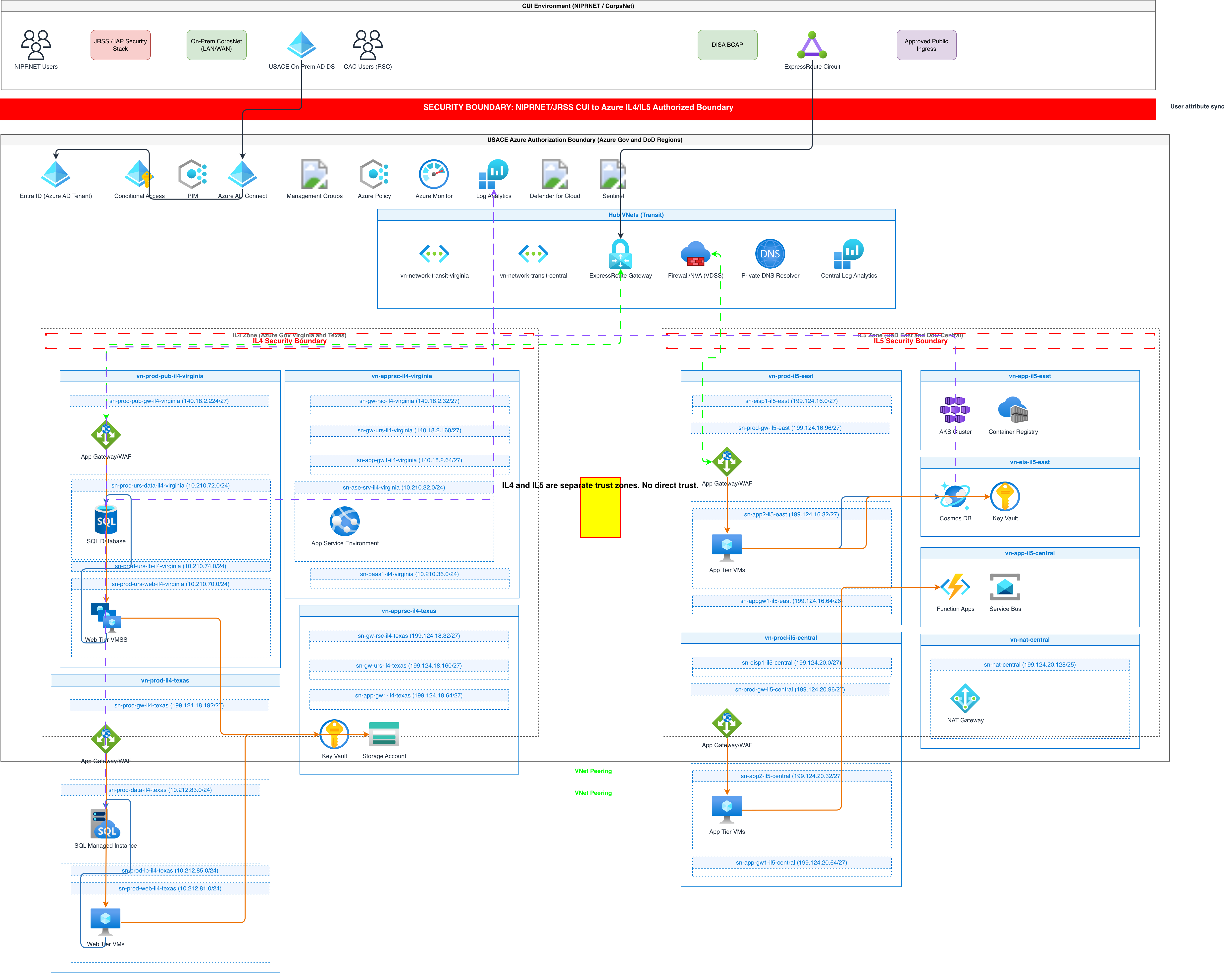
This AI Azure architecture diagram generator converts plain-text infrastructure descriptions into Draw.io diagrams with the official Microsoft Azure icon set. Describe a setup like 'Azure Front Door routing to App Service in East US 2 with VNet integration, Azure SQL Database with geo-replication to West US 2, and Azure Cache for Redis Premium tier in the same VNet.' The AI maps each service to its official Azure icon, draws resource group boundaries, places resources within VNet and subnet boundaries, and outputs valid mxGraphModel XML. Architecture warnings flag single-region deployments (WARN-01) and public endpoints without Azure Front Door WAF policies (WARN-02). Every element snaps to a 10px grid. The output is native .drawio XML.
What Is an AI Azure Architecture Diagram Generator?
An Azure architecture diagram maps your cloud infrastructure on the Microsoft Azure platform: resource groups, VNets, subnets, App Services, Azure Functions, AKS clusters, Azure SQL databases, and the networking between them. Building these diagrams manually means searching for the correct Azure icon, positioning resources within resource group and VNet boundaries, and drawing NSG rules and traffic flows by hand. An AI Azure architecture diagram generator automates the entire process. You write a natural-language description of your Azure infrastructure. The AI identifies each Azure service, selects the correct icon from the official Microsoft Azure Icon Set, and positions components within resource group containers and VNet boundaries. Diagrams.so applies Azure-specific layout conventions. Resource groups appear as top-level containers with the purple resource group icon as a header. VNets nest inside resource groups with address space labels (10.0.0.0/16). Subnets divide the VNet with their own CIDR ranges. NSGs attach to subnets or individual NICs with rule summaries showing port ranges and source/destination. The generator handles Azure's hub-spoke VNet topology. When you describe a hub VNet with Azure Firewall peered to spoke VNets with workloads, the AI draws VNet peering connections with bidirectional arrows and gateway transit labels. RULE-02 enforces official Azure icons for every service. RULE-06 groups resources by resource group. Architecture warning WARN-01 flags single-region deployments. WARN-02 catches public endpoints without WAF. WARN-03 identifies databases without geo-replication. VLM visual validation detects overlapping icons and illegible labels. The output is native .drawio XML that opens in Draw.io, Visual Studio, or Confluence.
Key components
- Resource group containers with the official purple resource group icon as header labels
- VNet boundaries with address space notation (10.0.0.0/16) and subnet segmentation with CIDR ranges
- Official Microsoft Azure Icon Set for 300+ services including App Service, Functions, AKS, Azure SQL, Cosmos DB
- NSG rule indicators at subnet or NIC level with port ranges (443, 8080) and allow/deny annotations
- Hub-spoke VNet topology with VNet peering arrows and gateway transit labels
- Azure Front Door or Application Gateway with WAF policy associations and routing rules
- Managed identity connections shown as dotted lines from App Services and Functions to Key Vault and Storage
- Architecture warnings for single-region (WARN-01), missing WAF (WARN-02), and no geo-replication (WARN-03)
How to generate with AI
- 1
Describe your Azure infrastructure
Write your architecture in plain English with specific Azure services, regions, and networking. For example: 'Resource group rg-prod-eastus2 in East US 2. VNet vnet-prod with 10.0.0.0/16. Subnet snet-web (10.0.1.0/24) with App Service plan P2v3 running two App Services. Subnet snet-data (10.0.2.0/24) with Azure SQL Database S3 tier and Azure Cache for Redis Premium P1. Azure Front Door with WAF policy routing to App Services. Managed identities on App Services accessing Key Vault for secrets. Application Insights for monitoring.' Include naming conventions and SKUs if you want them on the diagram.
- 2
Select diagram type and cloud provider
Choose 'Architecture' as the diagram type and 'Azure' as the cloud provider. Diagrams.so loads the official Microsoft Azure Icon Set with 300+ service icons. Enable opinionated mode to enforce resource group boundaries, VNet nesting, and hub-spoke layout when applicable. The AI follows RULE-02 for official icons and RULE-06 for resource group grouping.
- 3
Generate and validate
Click generate. The AI produces .drawio XML with resource group containers, VNet boundaries, subnet divisions, NSG indicators, and labeled traffic arrows. Architecture warnings flag single-region deployments (WARN-01), public endpoints without WAF (WARN-02), and databases without geo-replication (WARN-03). VLM visual validation catches overlapping icons. Download as .drawio for editing, or export to PNG or SVG for Azure landing zone documentation.
Example prompt
Azure hub-spoke production architecture in East US 2. Hub resource group rg-hub-eastus2: Hub VNet (10.0.0.0/16), Azure Firewall Premium in AzureFirewallSubnet (10.0.0.0/26), Azure Bastion in AzureBastionSubnet (10.0.1.0/26), VPN Gateway in GatewaySubnet (10.0.2.0/27) for site-to-site VPN to on-premises. Spoke 1 resource group rg-app-eastus2: Spoke VNet (10.1.0.0/16) peered to hub. Subnet snet-web (10.1.1.0/24) with App Service Environment v3. Subnet snet-api (10.1.2.0/24) with AKS cluster (3 nodes Standard_D4s_v5, cluster autoscaler min 3 max 12). Subnet snet-data (10.1.3.0/24) with Azure SQL Managed Instance Business Critical tier and Cosmos DB with multi-region writes. NSG on snet-web allows 443 from Azure Front Door service tag only. NSG on snet-data allows 1433 from snet-api only. Azure Front Door Premium with WAF policy in prevention mode routing /app to App Service and /api to AKS ingress. Managed identities accessing Key Vault and Storage Account. Application Insights and Log Analytics workspace for monitoring. Azure Monitor alerts for CPU > 80% and response time > 2s.
Example diagrams from the gallery


Azure VNet Architecture vs AWS VPC Architecture vs GCP VPC Architecture
Each cloud provider structures virtual networks differently. Azure uses VNets with resource groups. AWS uses VPCs with availability zones. GCP uses globally scoped VPCs with regional subnets. These structural differences change how architecture diagrams are organized and what boundaries appear.
| Feature | Azure VNet Architecture | AWS VPC Architecture | GCP VPC Architecture |
|---|---|---|---|
| Network scope | VNets are regional; subnets don't map to availability zones; zone redundancy is per-resource | VPCs are regional; each subnet maps to exactly one AZ; Multi-AZ requires duplicate subnets | VPCs are global; subnets are regional; no zone-specific subnet required |
| Resource grouping | Resource groups as logical containers; one resource group can span regions; diagrams use RG boundaries | No direct equivalent; tags and accounts provide grouping; diagrams use VPC and AZ columns | Projects as organizational unit; folders and org hierarchy above; diagrams use project boundaries |
| Firewall/security model | NSGs on subnets or NICs with priority-ordered rules; Azure Firewall for centralized inspection | Security groups on instances (stateful); NACLs on subnets (stateless); AWS WAF on ALB/CloudFront | VPC firewall rules with priority and tags; Cloud Armor for L7 protection; hierarchical policies |
| Hub-spoke topology | VNet peering with gateway transit; Azure Virtual WAN for large-scale; Azure Firewall in hub | Transit Gateway connecting VPCs; VPC peering for point-to-point; AWS Network Firewall in hub | Shared VPC across projects; VPC peering for cross-org; no separate hub VNet needed |
| Managed database placement | Azure SQL with Private Link or Managed Instance in dedicated subnet; Cosmos DB with VNet service endpoints | RDS in private subnets with security groups; subnet groups define AZ placement | Cloud SQL with private IP via VPC peering; Spanner and BigQuery are VPC-independent |
| Typical diagram layout | Resource group boxes containing VNets; subnets as horizontal bands; hub-spoke for enterprise | VPC as outer box; AZ columns inside; subnets stacked vertically per AZ | Project boundary; VPC as flat container; subnets labeled by region, not zone |
When to use this pattern
Use an Azure architecture diagram when you need to document infrastructure deployed on Microsoft Azure. Landing zone designs, hub-spoke network topologies, and App Service or AKS workload architectures are ideal candidates. It's the right choice when your team uses Azure-specific services like Azure Front Door, Azure SQL Managed Instance, Cosmos DB, or Azure Functions. If your infrastructure runs on AWS, use an AWS architecture diagram with VPC and AZ conventions instead. For GCP, use a GCP architecture diagram with global VPC and regional subnet layout. If your workload spans multiple clouds, create separate provider-specific diagrams and link them through a multi-cloud overview.
Frequently asked questions
Does the AI Azure architecture diagram generator use official Azure icons?
Yes. This AI Azure architecture diagram generator uses the official Microsoft Azure Icon Set with 300+ service icons. RULE-02 enforces official cloud provider icons for every Azure service. You get the correct icons for App Service, Azure Functions, AKS, Azure SQL, Cosmos DB, Key Vault, and all other Azure services. No generic shapes.
How does the AI represent resource groups?
Resource groups appear as labeled containers with the official purple resource group icon. All resources within a resource group are visually enclosed in its boundary. RULE-06 drives this grouping. If your prompt mentions multiple resource groups, each gets its own container with resources positioned inside.
Can I diagram hub-spoke VNet topologies?
Yes. Describe your hub VNet with Azure Firewall and gateway, then describe spoke VNets with their workloads. The AI draws VNet peering connections as bidirectional arrows with gateway transit labels. Azure Virtual WAN topologies are also supported. The hub-spoke layout is the default for opinionated mode when multiple VNets are present.
What architecture warnings apply to Azure diagrams?
WARN-01 flags single-region deployments without failover. WARN-02 catches public-facing App Services or Application Gateways without Azure Front Door WAF. WARN-03 identifies Azure SQL databases without geo-replication. WARN-04 detects missing NSG rules on subnets. WARN-05 flags ambiguously named resources. Warnings are non-blocking annotations.
Can I generate diagrams for Azure serverless architectures?
Yes. Describe your Azure Functions, Logic Apps, Event Grid topics, Service Bus queues, and Cosmos DB triggers. The AI uses the correct icon for each serverless service and draws event-driven connections with labeled arrows. Voice-to-diagram input is available for dictating your Azure architecture hands-free.
Related diagram generators
Generate AWS architecture diagrams from text
Describe your AWS infrastructure in plain English. Get a valid Draw.io diagram with official AWS icons, VPC boundaries, and Multi-AZ placement.
Generate GCP Architecture Diagrams from Text
Describe your Google Cloud infrastructure in plain English. Get a valid Draw.io diagram with official GCP icons, project boundaries, and VPC networking.
Generate Cloud Architecture Diagrams from Text
Describe your cloud infrastructure in plain English. Get a valid Draw.io diagram with region boundaries, availability zones, managed services, and DR paths.
Generate Kubernetes Diagrams from Text with AI
Describe your Kubernetes cluster in plain English. Get a valid Draw.io diagram with CNCF icons, namespace boundaries, deployments, services, and ingress controllers.