Generate OCI Networking Diagrams from Text with AI
Describe your Oracle Cloud network topology in plain English. Get a valid Draw.io diagram with VCN subnets, gateways, Security Lists, and DRG hub-spoke routing.
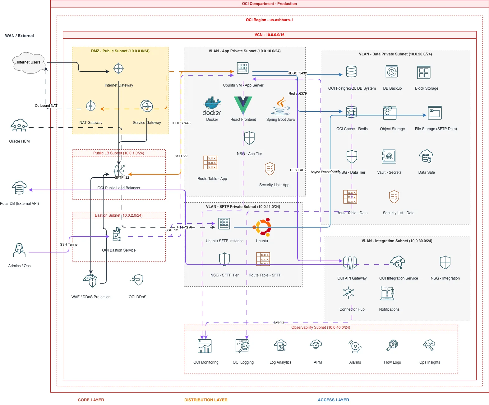
This OCI networking diagram generator converts plain-text network topology descriptions into Draw.io diagrams with Oracle Cloud networking icons. Describe a setup like a hub VCN (10.0.0.0/16) connected via Dynamic Routing Gateway to three spoke VCNs, with a public subnet hosting an OCI Load Balancer behind a WAF, private subnets using a NAT Gateway for outbound traffic, and a 10Gbps FastConnect to your on-premises data center. The AI maps each component to its correct Oracle networking icon, draws Security List rules as labeled boundaries, segments subnets by public and private designation, and outputs valid mxGraphModel XML. Architecture warnings flag public endpoints without WAF (WARN-02) and missing security boundaries between network tiers (WARN-04). Every element snaps to a 10px grid. The output opens directly in Draw.io.
What Is an OCI Networking Diagram Generator?
An OCI networking diagram maps the virtual network topology of your Oracle Cloud infrastructure: VCNs, subnets, gateways, Security Lists, Network Security Groups, and the routing paths between them. Building these manually means placing icons for each gateway type, drawing subnet boundaries, labeling CIDR ranges, and connecting route table entries. An OCI networking diagram generator does this from a text description. You write something like: 'Hub VCN (10.0.0.0/16) with a DRG attachment. Public subnet (10.0.1.0/24) with Internet Gateway. Private subnet (10.0.2.0/24) with NAT Gateway and Service Gateway for OCI object storage access. Spoke VCN (10.1.0.0/16) peered via DRG with route table sending 0.0.0.0/0 to hub. FastConnect 10Gbps from DRG to on-premises.' Diagrams.so parses this and produces a diagram with correct OCI networking icons from its icon library. VCNs render as boundary containers with CIDR labels. Subnets appear as color-coded segments distinguishing public from private. Each gateway type gets its own icon: Internet Gateway, NAT Gateway, Service Gateway, Local Peering Gateway, and DRG. Security Lists display as rule annotations on subnet boundaries. Network Security Groups render as dashed boundaries around grouped resources. The AI follows RULE-05 for left-to-right layout, placing external connectivity on the left and internal workloads on the right. WARN-02 fires when a subnet faces the internet without WAF or Security List restrictions. WARN-04 triggers when subnets lack explicit Security List or NSG rules. VLM visual validation catches overlapping CIDR labels on dense multi-VCN topologies. The .drawio output supports layered views for toggling between routing and security perspectives.
Key components
- VCN boundaries with CIDR notation (10.0.0.0/16) and subnet segmentation by public and private designation
- Internet Gateway, NAT Gateway, and Service Gateway icons with route table association labels
- Dynamic Routing Gateway (DRG) as central hub with VCN attachments, VPN tunnels, and FastConnect virtual circuits
- Security Lists with ingress/egress rule summaries displayed as annotations on subnet boundaries
- Network Security Groups as dashed boundaries around resource groups with port/protocol labels
- Local Peering Gateway connections for same-region VCN-to-VCN traffic with route table references
- FastConnect virtual circuits with bandwidth labels (1Gbps, 10Gbps) and BGP peering ASN annotations
- Hub-spoke topology layout with DRG at center and spoke VCNs radiating outward with route table arrows
How to generate with AI
- 1
Describe your OCI network topology
Write your network layout in plain English. Include VCN CIDRs, subnet designations, gateway types, and routing paths. For example: 'Hub-spoke network in us-ashburn-1. Hub VCN (10.0.0.0/16) with DRG, Internet Gateway, and NAT Gateway. Public subnet (10.0.1.0/24) for load balancers. Private subnet (10.0.2.0/24) for compute. Spoke A VCN (10.1.0.0/16) for production workloads. Spoke B VCN (10.2.0.0/16) for development. All spokes route through DRG to hub. FastConnect 10Gbps to on-premises via DRG.'
- 2
Select network diagram type and provider
Choose 'Network' as the diagram type and 'OCI' as the cloud provider. Diagrams.so loads Oracle Cloud networking icons including DRG, all gateway types, Security Lists, and NSGs from its 30+ icon libraries. Enable opinionated mode to enforce hub-spoke layout with external connectivity on the left and internal workloads on the right.
- 3
Generate and review
Click generate. The AI outputs .drawio XML with VCN boundaries, subnet segments, gateway icons, and DRG hub-spoke routing paths. Architecture warnings flag public subnets without WAF (WARN-02) and subnets missing Security List rules (WARN-04). VLM visual validation catches overlapping CIDR labels on multi-VCN layouts. Download as .drawio for editing in Draw.io, or export to PNG or SVG for network documentation.
Example prompt
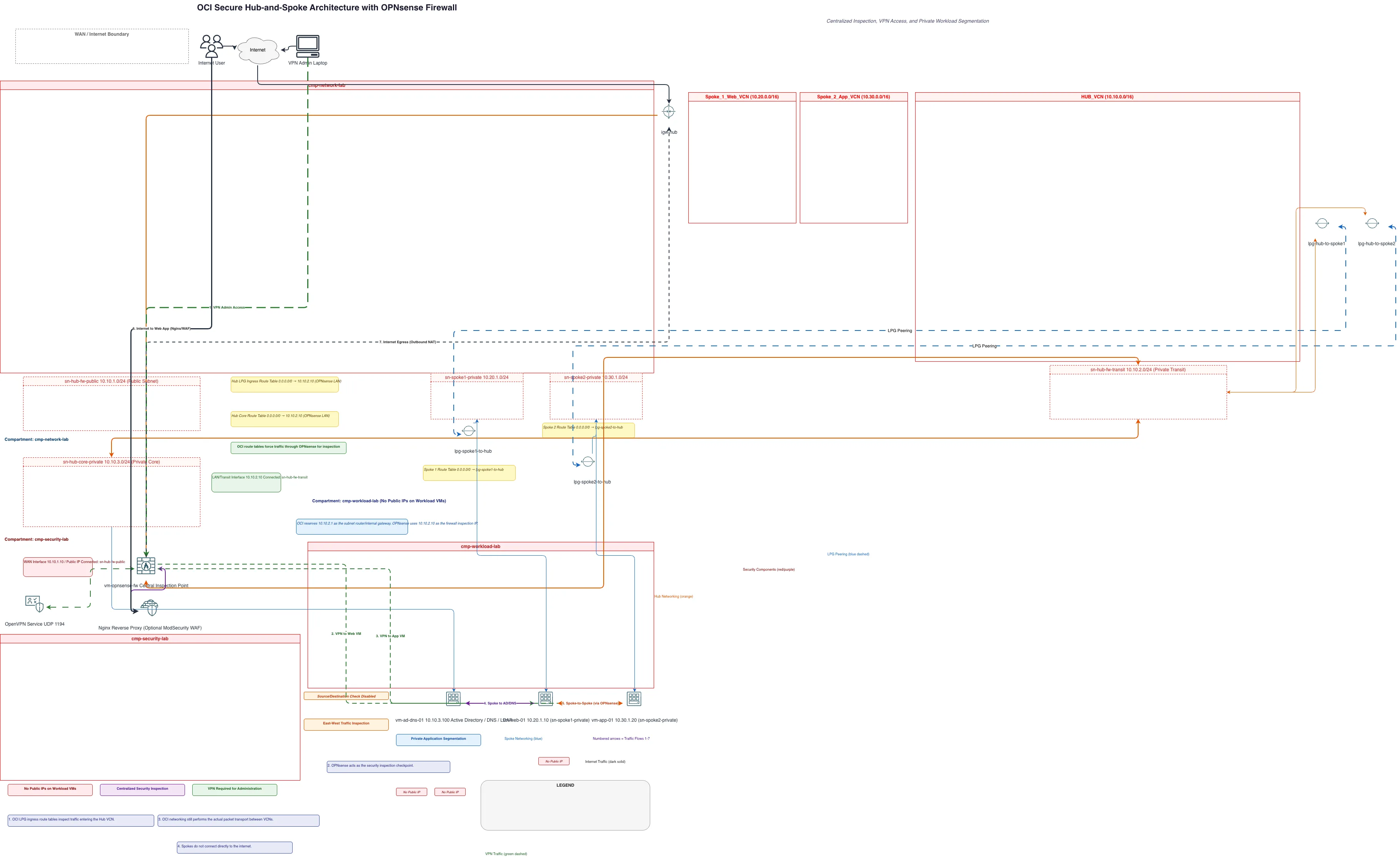
OCI hub-spoke network architecture in us-ashburn-1. Hub VCN (10.0.0.0/16): DRG v2 with four attachments. Public subnet (10.0.1.0/24) with Internet Gateway, OCI Load Balancer, and WAF policy. Private subnet (10.0.2.0/24) with NAT Gateway for outbound. Service Gateway for access to OCI Object Storage and Autonomous Database. Spoke 1 VCN (10.1.0.0/16): Production workloads. Private subnet (10.1.1.0/24) for compute instance pool. Private subnet (10.1.2.0/24) for Autonomous Transaction Processing private endpoint. Spoke 2 VCN (10.2.0.0/16): Development environment. Private subnet (10.2.1.0/24) for dev compute. DRG route tables: spoke-to-hub routes 0.0.0.0/0 via DRG, hub-to-spoke routes 10.1.0.0/16 and 10.2.0.0/16 via DRG. FastConnect 10Gbps virtual circuit from DRG to on-premises Cisco ASR 9001 with BGP ASN 65500. IPsec VPN backup tunnel to same on-premises router. Security Lists: public subnet allows 443 inbound from 0.0.0.0/0; private subnets allow traffic only from hub VCN CIDR. NSG on compute instances allows port 8080 from load balancer NSG only.
Example diagrams from the gallery
OCI VCN vs AWS VPC vs Azure VNet - Cloud Networking Compared
All three cloud providers offer virtual network constructs, but their models for subnets, security, gateways, and peering differ. OCI uses VCNs with explicit gateway types and Security Lists. AWS uses VPCs with security groups and NACLs. Azure uses VNets with NSGs and Azure Firewall. Understanding these differences determines how your network diagram is structured.
| Feature | OCI VCN | AWS VPC | Azure VNet |
|---|---|---|---|
| Subnet model | Subnets are regional or AD-specific; designated public or private at creation; CIDR assigned per subnet | Subnets are AZ-specific; public/private determined by route table pointing to Internet Gateway or NAT Gateway | Subnets are regional; not tied to zones; public/private controlled by NSG rules and route tables |
| Security filtering | Two layers: Security Lists (stateful, applied to entire subnet) and NSGs (stateful, applied to individual VNICs) | Security Groups (stateful, per-ENI) and NACLs (stateless, per-subnet); security groups are primary | NSGs (stateful) attached to subnets or NICs; Azure Firewall or third-party NVAs for centralized filtering |
| Gateway types | Five distinct gateways: Internet, NAT, Service, Local Peering, and DRG; each serves one function | Internet Gateway, NAT Gateway, VPN Gateway, Transit Gateway; fewer distinct types but broader per-gateway scope | VPN Gateway, ExpressRoute Gateway, NAT Gateway; Azure Firewall serves as a central routing and filtering point |
| Hub-spoke connectivity | DRG v2 as central hub with VCN attachments, route tables per attachment, and cross-tenancy peering support | Transit Gateway with route tables, attachment associations, and cross-account/cross-region peering | Azure Virtual WAN or hub VNet with VNet peering; Azure Firewall Manager for centralized policy |
| Dedicated connectivity | FastConnect with 1/10Gbps virtual circuits; BGP peering through DRG; partner or colocation models | Direct Connect with 1/10/100Gbps ports; virtual interfaces (public, private, transit) to VGW or TGW | ExpressRoute with 50Mbps to 100Gbps circuits; Global Reach for cross-circuit connectivity; private peering |
| Diagram layout pattern | DRG centered with spoke VCNs radiating outward; gateways shown as distinct icons on VCN boundaries | Transit Gateway centered with VPCs as surrounding boxes; IGW and NAT GW inline on subnet edges | Hub VNet with Azure Firewall at center; spoke VNets peered via dotted lines; ExpressRoute circuit on edge |
When to use this pattern
Use an OCI networking diagram when you need to document VCN topology, Security List rules, DRG routing configurations, or FastConnect connectivity to on-premises. It's the right choice for hub-spoke network designs, multi-VCN peering architectures, and hybrid connectivity planning with FastConnect and IPsec VPN backup tunnels. If your focus is on the application tier and services running inside the network rather than the network fabric itself, use an OCI architecture diagram instead. For physical network equipment like switches and routers in your on-premises data center, use a standard network diagram. Keep OCI networking diagrams focused on one hub-spoke topology or one VCN to maintain readability.
Frequently asked questions
Can the generator show Security Lists and NSG rules?
Yes. Describe your Security List rules or NSG rules in the prompt. The AI renders Security Lists as rule annotations on subnet boundaries showing allowed ports and protocols. Network Security Groups appear as dashed boundaries around grouped resources. This OCI networking diagram makes both security layers visible on a single view.
How does the AI handle DRG hub-spoke topologies?
Describe your DRG with its VCN attachments, route tables, and external connections. The AI places the DRG as a central hub icon with spoke VCNs radiating outward. Each attachment arrow carries its route table label. FastConnect and VPN connections appear as external links entering the DRG from the left.
Can I include FastConnect and VPN tunnels?
Yes. Specify FastConnect bandwidth, BGP ASN, and the on-premises router in your prompt. The AI draws FastConnect as a dedicated link with bandwidth labels and BGP peering details. IPsec VPN tunnels render as dashed lines with encryption annotations. Both connect through the DRG to your VCN topology.
What architecture warnings apply to OCI networking diagrams?
WARN-02 fires when a public subnet has internet-facing resources without OCI WAF or restrictive Security List rules. WARN-04 triggers when subnets lack explicit security filtering via Security Lists or NSGs. WARN-01 flags network designs confined to a single availability domain without redundant paths.
Does it support Service Gateway and private OCI service access?
Yes. Mention the Service Gateway and which OCI services you need private access to. The AI renders the Service Gateway as a gateway icon on the VCN boundary with labeled arrows pointing to OCI Object Storage, Autonomous Database, or other supported services. No internet transit shown for these paths.
Related diagram generators
Generate OCI Architecture Diagrams from Text with AI
Describe your Oracle Cloud infrastructure in plain English. Get a valid Draw.io diagram with compartment hierarchies, VCN boundaries, and availability domain placement.
Generate Network Diagrams from Text with AI
Describe your network topology in plain English. Get a valid Draw.io diagram with routers, switches, firewalls, VLAN segmentation, and labeled subnet ranges.
Generate Azure networking diagrams from text
Describe your Azure network topology in plain English. Get a valid Draw.io diagram with hub-spoke VNets, Azure Firewall rules, NSG flows, and Private Link endpoints.
Generate GCP Networking Diagrams from Text
Describe your Google Cloud network topology in plain English. Get a valid Draw.io diagram with Shared VPC, Cloud Armor, Cloud Router, and firewall policies using official GCP icons.