Generate Serverless Architecture Diagrams from Text with AI
Describe your serverless components and event triggers in plain English. Get a valid Draw.io diagram with Lambda functions, API Gateway, and managed services.
This AI serverless architecture diagram generator converts plain-text serverless descriptions into Draw.io diagrams with correct icons for Lambda, API Gateway, DynamoDB, S3, Step Functions, EventBridge, and other managed services. Describe an image processing pipeline where S3 PutObject events trigger a Lambda function that extracts metadata, writes to DynamoDB, publishes a thumbnail request to an SQS queue, and a second Lambda consumes the queue to generate thumbnails using Sharp and stores results back in S3. The AI maps each component to its official AWS icon, draws event trigger connections, and groups functions by domain. Every element snaps to a 10px grid per RULE-04. Architecture warnings flag single-AZ configurations (WARN-01) and public endpoints without WAF (WARN-02). The output is native .drawio XML.
What Is an AI Serverless Architecture Diagram Generator?
A serverless architecture diagram shows how event-driven compute functions, managed services, and triggers connect to form an application without visible server management. These architectures rely on AWS Lambda, Azure Functions, Google Cloud Run, API Gateway, DynamoDB, S3, Step Functions, and EventBridge. Diagramming them manually means finding vendor-specific icons, drawing event trigger arrows, and grouping functions into logical domains. The event-driven nature makes layout tricky because flows aren't linear. An AI serverless architecture diagram generator handles this complexity. You describe your serverless application. The AI identifies compute functions, triggers, managed services, and data stores, then generates the diagram with correct icons and connections. Diagrams.so recognizes serverless patterns across all three major clouds. Describe 'API Gateway with Lambda authorizer, three route Lambdas, and DynamoDB per-route tables' and the output shows API Gateway routing to individual functions with dedicated table connections. Describe 'Step Functions orchestrating four Lambda stages with retry policies and a DLQ fallback' and the diagram renders the state machine with stage transitions, retry loops, and dead letter queue branches. Mention 'EventBridge rule matching order.placed events routing to three target Lambdas' and you see fan-out event distribution. The AI enforces RULE-05 for left-to-right event flow layout. RULE-06 groups functions by domain into labeled containers. Opinionated mode prevents layout changes that break event flow sequence. VLM visual validation catches overlapping Lambda icons and tangled trigger arrows. WARN-02 flags API Gateway endpoints without WAF. WARN-01 identifies single-region DynamoDB tables without global tables. The output is native .drawio XML with icons from 30+ libraries.
Key components
- Compute functions: AWS Lambda, Azure Functions, Google Cloud Run with runtime and memory annotations
- API Gateway: REST/HTTP/WebSocket endpoints with route mapping, Lambda authorizers, and usage plans
- Event triggers: S3 notifications, SQS consumers, EventBridge rules, SNS subscriptions, DynamoDB Streams
- Orchestration: Step Functions state machines with Task, Choice, Parallel, and Wait states
- Data stores: DynamoDB tables with GSI annotations, S3 buckets with lifecycle rules, Aurora Serverless v2
- Dead letter queues: SQS DLQ and SNS DLQ branches for failed invocations with retry count labels
- Domain grouping: functions organized into labeled containers (auth, orders, notifications) per RULE-06
- Cold start and concurrency annotations showing reserved concurrency and provisioned concurrency settings
How to generate with AI
- 1
Describe your serverless application
Write your serverless architecture in plain English. Name every function, trigger, and managed service. For example: 'API Gateway HTTP API with /orders POST route. Lambda authorizer validates JWT from Cognito. OrderCreate Lambda validates request body, writes to DynamoDB orders table with orderId partition key, publishes order.created event to EventBridge default bus. EventBridge rule matches order.created and targets three Lambdas: InventoryReserve (updates DynamoDB inventory table), PaymentCharge (calls Stripe API), and NotificationSend (sends order confirmation via SES). If PaymentCharge fails after 3 retries, message goes to SQS dead letter queue. Step Functions orchestrates the saga with compensating transactions.'
- 2
Select serverless type and cloud provider
Choose 'Serverless' as the diagram type. Select your cloud provider (AWS, GCP, Azure) to load the matching icon library. AWS loads Lambda, API Gateway, DynamoDB, Step Functions, EventBridge, SQS, SNS, and S3 icons. GCP loads Cloud Run, Cloud Functions, Firestore, Pub/Sub, and Workflows icons. Azure loads Functions, API Management, Cosmos DB, and Event Grid icons. Enable opinionated mode for strict event-flow layout.
- 3
Generate and validate
Click generate. The AI outputs a .drawio XML with function icons, trigger arrows, managed service connections, and domain groupings. VLM visual validation flags overlapping icons and crossed trigger lines. Architecture warnings identify risks: API Gateway without WAF (WARN-02), single-region DynamoDB (WARN-01), and functions with ambiguous responsibilities (WARN-05). Download as .drawio, or export to PNG or SVG for architecture review documents.
Example prompt
Serverless architecture for a SaaS webhook processing platform on AWS: API Gateway HTTP API receives inbound webhooks on /webhooks/{provider} routes (Stripe, GitHub, Twilio). Lambda authorizer validates HMAC signatures per provider. WebhookRouter Lambda parses the event type and publishes to EventBridge custom bus 'webhook-events' with detail-type matching the provider event (e.g., stripe.invoice.paid, github.push). EventBridge rules route events to domain-specific Lambdas: PaymentProcessor for Stripe events (writes to DynamoDB payments table, calls internal billing API), RepoSyncProcessor for GitHub events (triggers CodeBuild via SDK), and AlertProcessor for Twilio events (sends to SNS topic for SMS alerts). Each Lambda has a dedicated SQS dead letter queue with 3 retry attempts. Step Functions orchestrates multi-step webhook flows that require saga-pattern compensation. S3 stores raw webhook payloads with 90-day lifecycle transition to Glacier. CloudWatch Logs with 30-day retention for all Lambda invocations.
Example diagrams from the gallery


Serverless Architecture vs Container Architecture vs VM-Based Architecture
These three architecture styles represent different points on the operational responsibility spectrum. Serverless delegates all infrastructure management to the cloud provider. Container architectures manage orchestration but not the OS. VM-based architectures manage everything from the operating system up.
| Feature | Serverless Architecture | Container Architecture | VM-Based Architecture |
|---|---|---|---|
| Compute model | Event-driven functions with per-invocation billing; Lambda, Cloud Functions, Azure Functions scale to zero | Long-running containers orchestrated by Kubernetes, ECS, or Cloud Run with minimum replica counts | Persistent virtual machines (EC2, Compute Engine, Azure VMs) running continuously with OS-level control |
| Scaling behavior | Automatic per-request scaling with concurrency limits; scales to zero when idle with possible cold starts | Horizontal pod autoscaler or target tracking policies; minimum replica count prevents scale-to-zero | Auto Scaling Groups or Managed Instance Groups with launch templates; minutes to provision new instances |
| Diagram complexity | Many small nodes with event trigger arrows; fan-out patterns create dense connection graphs | Fewer nodes (services) with service mesh or load balancer connections; namespace boundaries | Fewest nodes but largest; each VM box contains application stack details and OS-level components |
| State management | Externalized to DynamoDB, S3, ElastiCache, or Step Functions; functions are stateless by design | Stateless containers with external state stores; StatefulSets for databases with persistent volumes | Local disk, in-memory state, or external databases; session affinity via sticky load balancer sessions |
| Failure handling | Built-in retry policies, dead letter queues (SQS/SNS DLQ), Step Functions catch/retry states | Kubernetes restart policies, liveness/readiness probes, circuit breakers via service mesh (Istio/Linkerd) | Health checks with instance replacement, application-level retry logic, process supervisors (systemd) |
| Best suited for | Webhook processing, image transformation, scheduled jobs, event-driven microservices with variable load | API services, gRPC backends, ML inference endpoints, services requiring persistent connections or WebSockets | Legacy applications, GPU workloads, databases requiring local SSD, applications with OS-level dependencies |
When to use this pattern
Use a serverless architecture diagram when your application is built primarily on event-driven managed services like Lambda, API Gateway, DynamoDB, and EventBridge. These diagrams are essential for architecture design reviews before building new serverless applications, cost optimization discussions where per-invocation pricing matters, and onboarding engineers who need to trace event flows across many small functions. If your application runs on Kubernetes with long-running services, a container architecture diagram better represents pods, services, and ingress controllers. If you're documenting EC2 instances with custom AMIs and user data scripts, a VM-based infrastructure diagram is the right choice. Serverless diagrams work best when the architecture has clear event trigger chains.
Frequently asked questions
What serverless services does the AI serverless architecture diagram generator support?
This AI serverless architecture diagram generator supports AWS Lambda, API Gateway (REST, HTTP, WebSocket), DynamoDB, S3, Step Functions, EventBridge, SQS, SNS, SES, Cognito, Azure Functions, Azure Event Grid, Cosmos DB, Google Cloud Functions, Cloud Run, Pub/Sub, and Firestore. Each renders with its official icon from the 30+ available libraries.
How are event triggers shown in the diagram?
Event triggers render as labeled arrows from the source to the target function. S3 PutObject notifications, SQS queue consumers, EventBridge rule matches, DynamoDB Streams, and SNS subscriptions each use a distinct arrow style. Labels specify the event type, like 's3:ObjectCreated:*' or EventBridge detail-type. Trigger arrows use consistent color coding per source service.
Can I show Step Functions state machines in the diagram?
Yes. Describe the state machine stages in your prompt: 'Step Functions orchestrates ValidateOrder, ChargePayment, ReserveInventory, and SendConfirmation with retry on ChargePayment and DLQ fallback.' The AI renders Task, Choice, Parallel, and Wait states with transition arrows, retry indicators, and catch branches to error handlers.
Does the diagram include dead letter queue flows?
Yes. Mention DLQ in your prompt and the AI draws a failure branch from the Lambda or SQS consumer to the dead letter queue. The arrow label includes the max retry count. This makes failed invocation paths visible alongside the happy path, which is critical for operational runbook documentation and incident response planning.
Can I diagram multi-region serverless architectures?
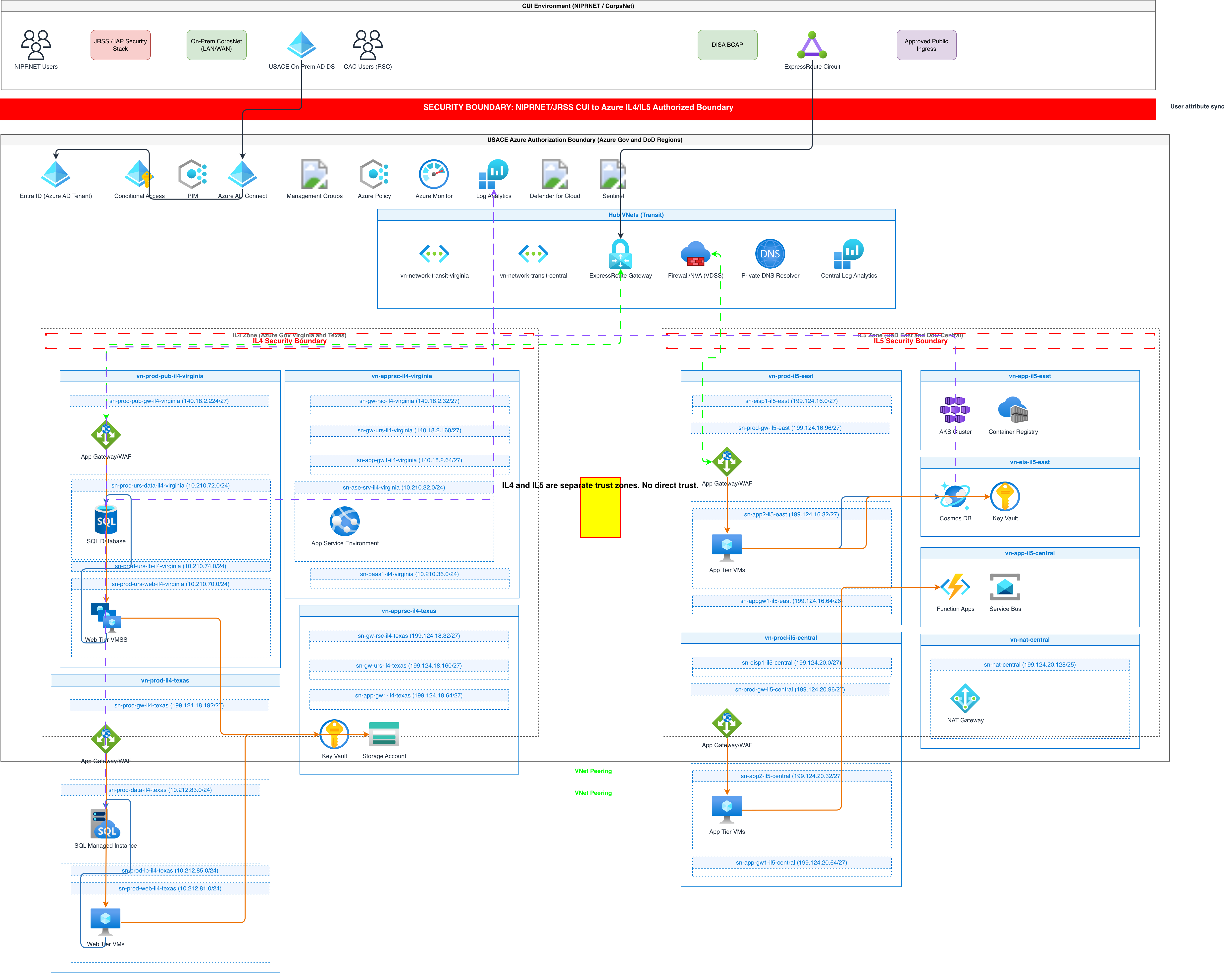
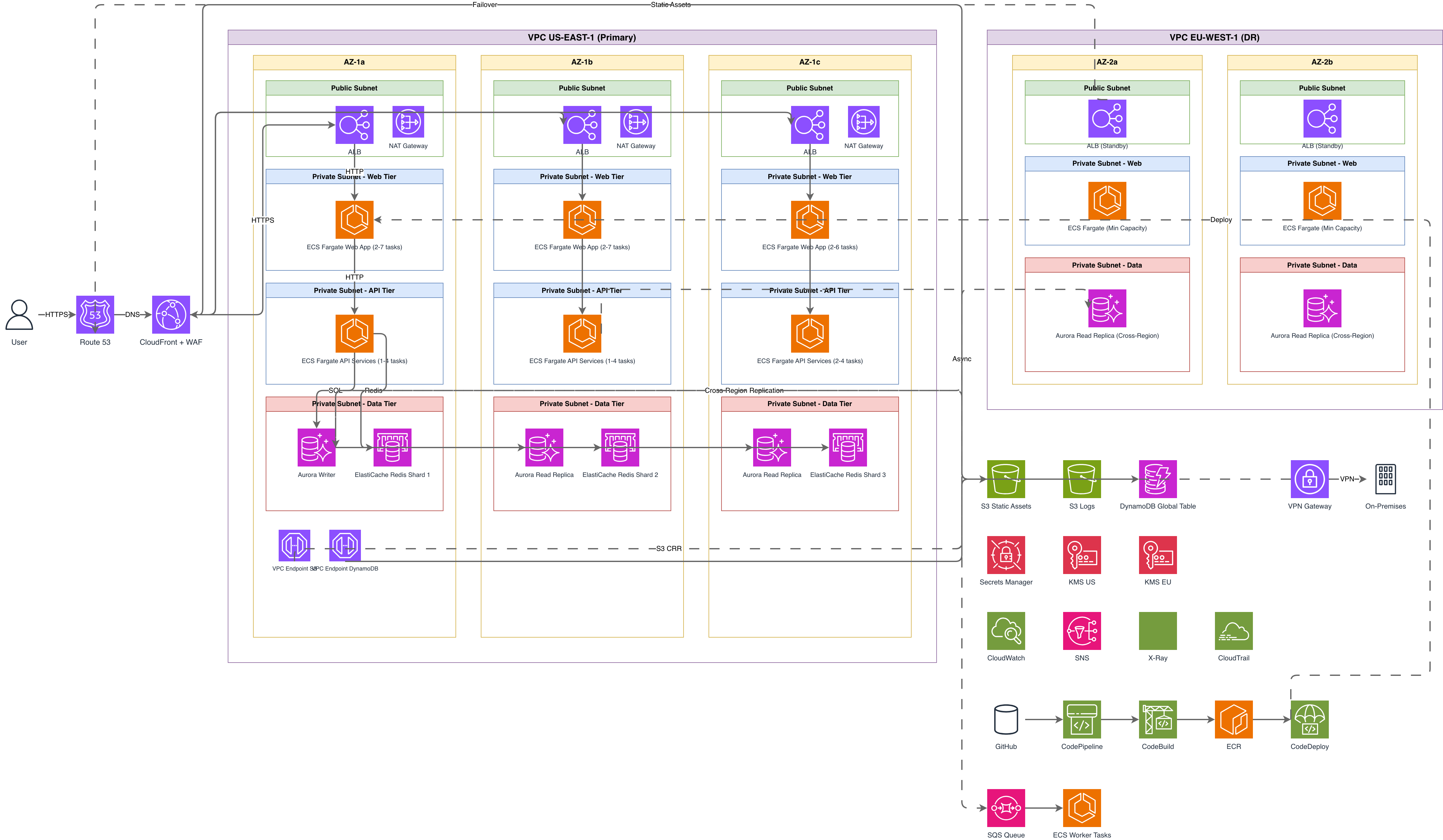
Yes. Describe the regions in your prompt: 'Lambda in us-east-1 and eu-west-1 with DynamoDB global tables.' The AI creates region containers with replicated components and cross-region replication arrows. WARN-01 does not trigger for multi-region setups since redundancy is already present. Route 53 routing policies connect the entry points.
Related diagram generators
Generate AWS architecture diagrams from text
Describe your AWS infrastructure in plain English. Get a valid Draw.io diagram with official AWS icons, VPC boundaries, and Multi-AZ placement.
Generate Event-Driven Architecture Diagrams from Text with AI
Describe your event producers, brokers, and consumers in plain English. Get a valid Draw.io diagram with Kafka topics, saga patterns, and DLQ flows.
Generate API Gateway Diagrams from Text with AI
Describe your API gateway routing, auth, and rate limiting in plain English. Get a valid Draw.io diagram with request flows, middleware chains, and backend services.
Generate Cloud Architecture Diagrams from Text
Describe your cloud infrastructure in plain English. Get a valid Draw.io diagram with region boundaries, availability zones, managed services, and DR paths.