Generate GKE Architecture Diagrams from Text
Describe your Google Kubernetes Engine cluster in plain English. Get a valid Draw.io diagram with GKE Autopilot, Anthos Service Mesh, Gateway API, and Workload Identity Federation.
This GKE architecture diagram generator converts plain-text cluster descriptions into Draw.io diagrams with official GCP and CNCF icons for GKE Autopilot, Standard clusters, Anthos Service Mesh, and Gateway API resources. Describe a production setup: GKE Autopilot cluster in us-central1 with three namespaces, Anthos Service Mesh handling mTLS between services, Gateway API HTTPRoute resources directing traffic from a global external Application Load Balancer, and Workload Identity Federation binding Kubernetes service accounts to GCP IAM. The AI maps each component to its correct icon, draws namespace boundaries, and routes service mesh connections with mTLS annotations. Grid alignment follows RULE-04. Architecture warnings flag single-zone node placement (WARN-01) and namespaces without network policies (WARN-04). Output is native .drawio XML.
What Is a GKE Architecture Diagram?
A GKE architecture diagram maps the components of a Google Kubernetes Engine cluster: node pools, namespaces, workloads, service mesh configuration, ingress routing, and surrounding GCP services. These diagrams differ from generic Kubernetes diagrams because they include GKE-specific constructs like Autopilot mode, node auto-provisioning, Config Connector for managing GCP resources as Kubernetes objects, and Workload Identity Federation for IAM binding. Building one manually means combining CNCF Kubernetes icons with GCP service icons, drawing cluster boundaries inside VPC subnets, and connecting pods to Cloud SQL, Pub/Sub, or Cloud Storage. An AI GKE architecture diagram generator handles this from a text prompt. Describe 'GKE Autopilot cluster in us-central1 inside a Shared VPC service project. Anthos Service Mesh with strict mTLS. Three namespaces: frontend, backend, data. Frontend runs a Next.js deployment behind a Gateway API HTTPRoute. Backend runs FastAPI pods connecting to Cloud SQL PostgreSQL via Private Service Connect. Data namespace runs a Spark operator job reading from BigQuery.' Diagrams.so selects the right icons from its 30+ libraries, draws the cluster boundary inside the VPC subnet, and groups workloads by namespace per RULE-06. RULE-05 enforces left-to-right traffic flow from ingress through the mesh to external services. Opinionated mode prevents layout drift. VLM visual validation catches overlapping pod icons in dense namespace views. WARN-01 flags single-zone clusters. WARN-02 detects services exposed via LoadBalancer without Cloud Armor. WARN-04 identifies namespaces missing network policies. The .drawio output is version-controllable alongside Helm charts and Kustomize overlays.
Key components
- GKE Autopilot cluster boundary with region label, release channel, and control plane version annotations
- Namespace containers with resource quota labels, LimitRange annotations, and network policy indicators
- Anthos Service Mesh sidecar proxies attached to pods with mTLS mode labels (STRICT, PERMISSIVE)
- Gateway API resources: GatewayClass, Gateway, HTTPRoute, and HealthCheckPolicy with routing rule labels
- Workload Identity Federation bindings showing Kubernetes SA to GCP IAM service account mappings
- Binary Authorization policy enforcement points between Artifact Registry and pod admission
- Config Connector resources managing Cloud SQL, Pub/Sub, and Cloud Storage as Kubernetes custom resources
- Multi-cluster Gateway with MCS ServiceExport and ServiceImport arrows across regional clusters
How to generate with AI
- 1
Describe your GKE cluster architecture
Write your GKE setup in plain English. Specify Autopilot or Standard mode, region, and namespace structure. For example: 'GKE Autopilot cluster autopilot-prod-usc1 in us-central1, rapid release channel. Shared VPC service project connected to host project network-prod. Three namespaces: frontend (Next.js deployment, 3 min replicas, HPA to 20), backend (FastAPI deployment with Cloud SQL Auth Proxy sidecar, 5 min replicas), and jobs (Cloud Scheduler triggered CronJobs). Anthos Service Mesh with STRICT mTLS. Gateway API with global external Application Load Balancer.'
- 2
Select GCP and architecture type
Set cloud provider to GCP and diagram type to Architecture. Diagrams.so loads both official GCP icons and CNCF Kubernetes icons, covering GKE, Cloud SQL, Pub/Sub, Cloud Storage, and every Kubernetes resource type. Enable opinionated mode to enforce namespace grouping, ingress-to-backend left-to-right flow, and automatic placement of GCP external services outside the cluster boundary.
- 3
Generate and validate
Click generate. The AI produces a .drawio XML with the GKE cluster boundary inside a VPC subnet, namespace groupings, mesh connections with mTLS labels, and Workload Identity bindings drawn as arrows from Kubernetes SAs to GCP SAs. Architecture warnings flag single-zone clusters (WARN-01), internet-exposed services without Cloud Armor (WARN-02), and namespaces without network policies (WARN-04). VLM visual validation checks for overlapping icons. Download as .drawio, PNG, or SVG.
Example prompt
GKE production architecture: GKE Autopilot cluster autopilot-prod in us-central1 on rapid release channel inside Shared VPC service project app-prod connected to host project network-prod subnet gke-pods-usc1 (10.4.0.0/14). Anthos Service Mesh 1.20 with STRICT mTLS across all namespaces. Gateway API: GatewayClass gke-l7-global-external-managed, Gateway with HTTPS listener on port 443 using Google-managed certificate. HTTPRoute routes /app to frontend-svc and /api to backend-svc. Namespace frontend: Next.js deployment (3 replicas, HPA to 20 at 70% CPU), ClusterIP service on port 3000. Namespace backend: FastAPI deployment (5 replicas, HPA to 30 at 60% CPU) with Cloud SQL Auth Proxy sidecar connecting to Cloud SQL PostgreSQL 15 in us-central1 via Private Service Connect. Workload Identity Federation binds backend-sa KSA to backend-gcp@app-prod.iam.gserviceaccount.com. Namespace jobs: CronJob running Dataflow job launcher triggered by Cloud Scheduler every hour. Binary Authorization enforces attestation from Cloud Build before pod admission. Artifact Registry docker repo in us-central1 stores all container images. Config Connector manages Pub/Sub topics and Cloud Storage buckets as Kubernetes resources.
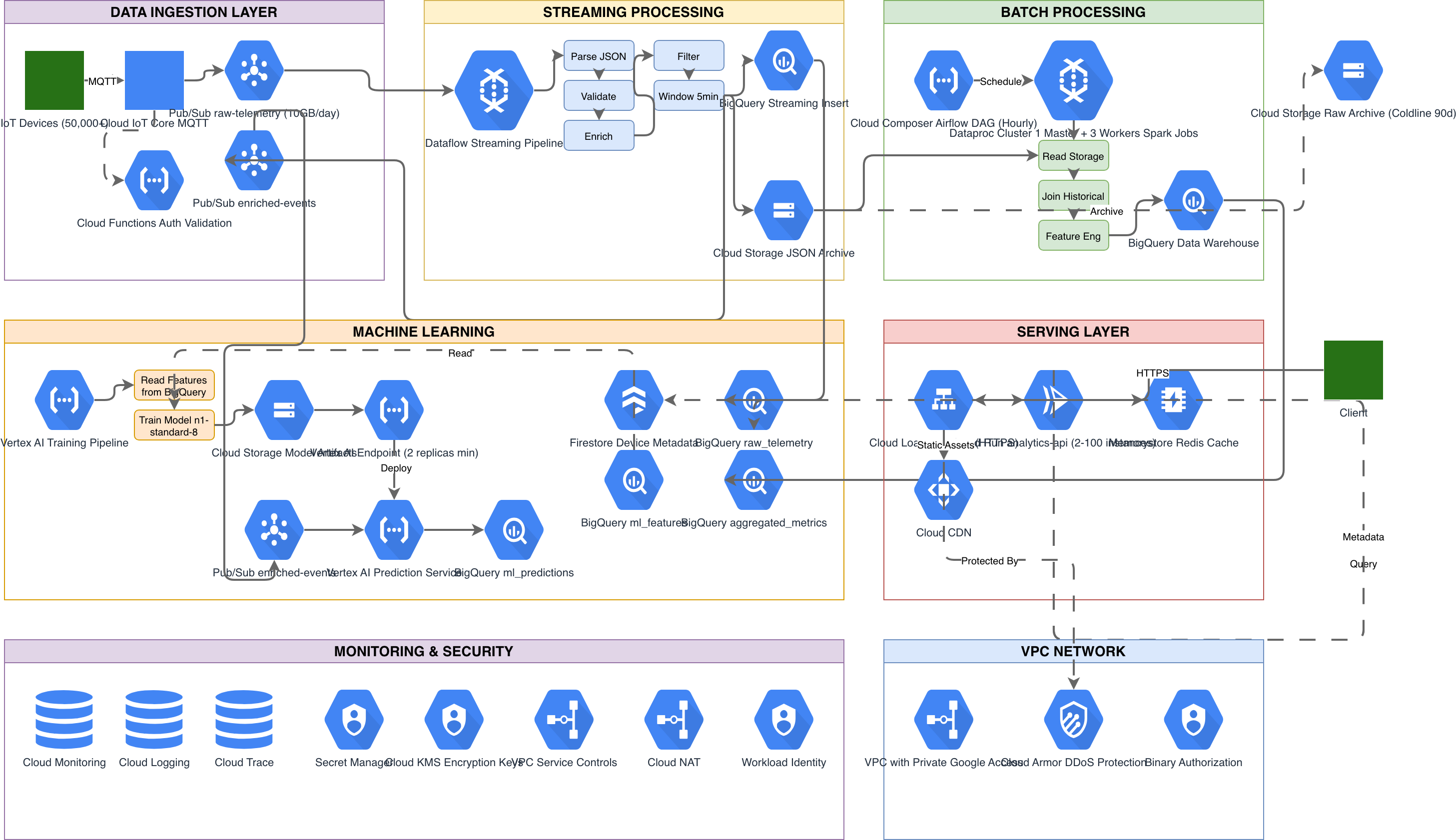
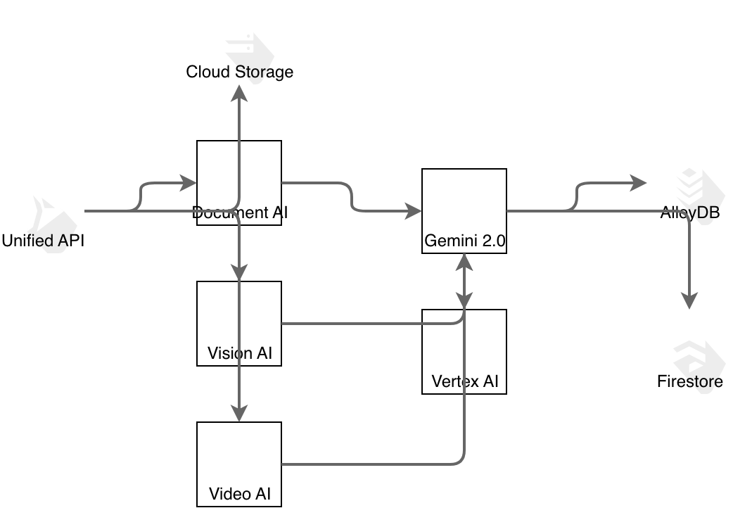
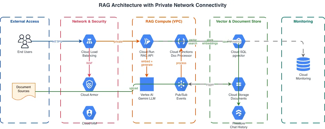
Example diagrams from the gallery

GKE Autopilot vs GKE Standard vs Cloud Run
Google Cloud offers three primary container runtime options. GKE Autopilot manages nodes and infrastructure automatically. GKE Standard gives full control over node pools and machine types. Cloud Run abstracts the cluster entirely and scales containers to zero. Each suits different operational models and cost profiles.
| Feature | GKE Autopilot | GKE Standard | Cloud Run |
|---|---|---|---|
| Node management | Fully managed by Google; no node pools to configure, no machine types to choose, no node SSH access | You create and manage node pools with specific machine types, GPUs, spot instances, and autoscaling ranges | No nodes; Google provisions compute per request or instance; you configure CPU, memory, and concurrency per service |
| Pricing model | Pay per pod resource request (vCPU, memory, ephemeral storage); no charge for unused node capacity | Pay for provisioned nodes regardless of pod utilization; cluster management fee of $0.10/hour per cluster | Per-request pricing with CPU allocated only during request processing, or always-on CPU with minimum instances |
| Scaling behavior | HPA scales pods; Google auto-provisions nodes to fit pod requests; no manual node scaling | HPA for pods, Cluster Autoscaler for nodes with configurable min/max per node pool; NAP optional | Scales from zero to thousands of instances based on concurrent requests; cold start latency on scale-from-zero |
| Service mesh support | Anthos Service Mesh managed control plane with automatic sidecar injection; supports Istio APIs | Anthos Service Mesh or self-managed Istio; full control over sidecar resources and control plane versioning | No service mesh; inter-service auth via IAM invoker permissions and service-to-service identity tokens |
| Networking model | Gateway API or GKE Ingress; VPC-native with alias IP ranges; Private Service Connect for GCP APIs | Same as Autopilot plus custom CNI options, Dataplane V2 (Cilium), and node-level network policies | Automatic HTTPS endpoint; VPC connector or Direct VPC egress for private resource access; no pod networking |
| Best suited for | Teams wanting Kubernetes APIs without node ops; predictable pod-level billing; compliance workloads needing Binary Authorization | GPU workloads, custom kernel modules, Windows containers, workloads requiring specific machine families or sole tenancy | Stateless HTTP services, webhook handlers, event-driven microservices that benefit from scale-to-zero cost savings |
When to use this pattern
Use a GKE architecture diagram when you need to document cluster topology, namespace layout, service mesh configuration, or the connection between GKE workloads and surrounding GCP services. It's the right choice for platform team design reviews, security audits of Workload Identity and Binary Authorization policies, and onboarding engineers to a multi-namespace cluster. If your architecture spans the full GCP project hierarchy with Shared VPCs and multiple services beyond Kubernetes, start with a GCP architecture diagram and drill into GKE detail separately. For Cloud Run deployments that don't use Kubernetes primitives, a serverless architecture diagram fits better. Don't overload a GKE diagram with application-level business logic; use sequence diagrams for inter-service communication flows.
Frequently asked questions
Does the GKE architecture diagram generator show Autopilot-specific details?
Yes. When you specify GKE Autopilot in your prompt, the AI omits node pool configurations since Google manages them. It focuses on pod resource requests, Autopilot compute classes (general-purpose, balanced, scale-out), and the cluster boundary without node-level detail. This GKE architecture diagram reflects the operational model where you manage workloads, not infrastructure.
Can I include Anthos Service Mesh in the diagram?
Yes. Describe your mesh setup: 'Anthos Service Mesh with STRICT mTLS, AuthorizationPolicies restricting backend access to frontend only.' The AI draws Envoy sidecar proxies attached to pods, mTLS connection labels between services, and AuthorizationPolicy rules as annotations. Mesh control plane components render outside the namespace boundaries.
How does the AI represent Workload Identity Federation?
Mention the binding in your prompt: 'Kubernetes SA backend-sa in namespace backend bound to GCP SA backend@project.iam.' The AI draws an arrow from the Kubernetes service account icon to the GCP IAM service account icon with the binding annotation. This makes IAM trust relationships visible alongside the cluster topology.
What architecture warnings apply to GKE diagrams?
WARN-01 flags single-zone clusters or deployments with one replica. WARN-02 catches services exposed via external load balancers without Cloud Armor WAF policies. WARN-04 detects namespaces missing NetworkPolicy definitions, leaving pod-to-pod traffic unrestricted. WARN-05 flags vague resource names that need specificity.
Can I diagram multi-cluster GKE with Multi-Cluster Services?
Yes. Describe your multi-cluster topology: 'GKE cluster in us-central1 and us-east1 with Multi-Cluster Gateway. ServiceExport in us-central1 backend namespace, ServiceImport in us-east1.' The AI draws both cluster boundaries with MCS export and import arrows between them, showing cross-cluster service discovery and traffic routing.
Related diagram generators
Generate Kubernetes Diagrams from Text with AI
Describe your Kubernetes cluster in plain English. Get a valid Draw.io diagram with CNCF icons, namespace boundaries, deployments, services, and ingress controllers.
Generate GCP Architecture Diagrams from Text
Describe your Google Cloud infrastructure in plain English. Get a valid Draw.io diagram with official GCP icons, project boundaries, and VPC networking.
Generate AKS Architecture Diagrams from Text with AI
Describe your Azure Kubernetes Service cluster in plain English. Get a valid Draw.io diagram with node pools, Azure CNI networking, AGIC ingress, and KEDA autoscaling.
Generate Microservices Architecture Diagrams from Text
Describe your service boundaries in plain English. Get a valid Draw.io diagram with API gateways, message brokers, database-per-service patterns, and service mesh routing.