Generate AKS Architecture Diagrams from Text with AI
Describe your Azure Kubernetes Service cluster in plain English. Get a valid Draw.io diagram with node pools, Azure CNI networking, AGIC ingress, and KEDA autoscaling.
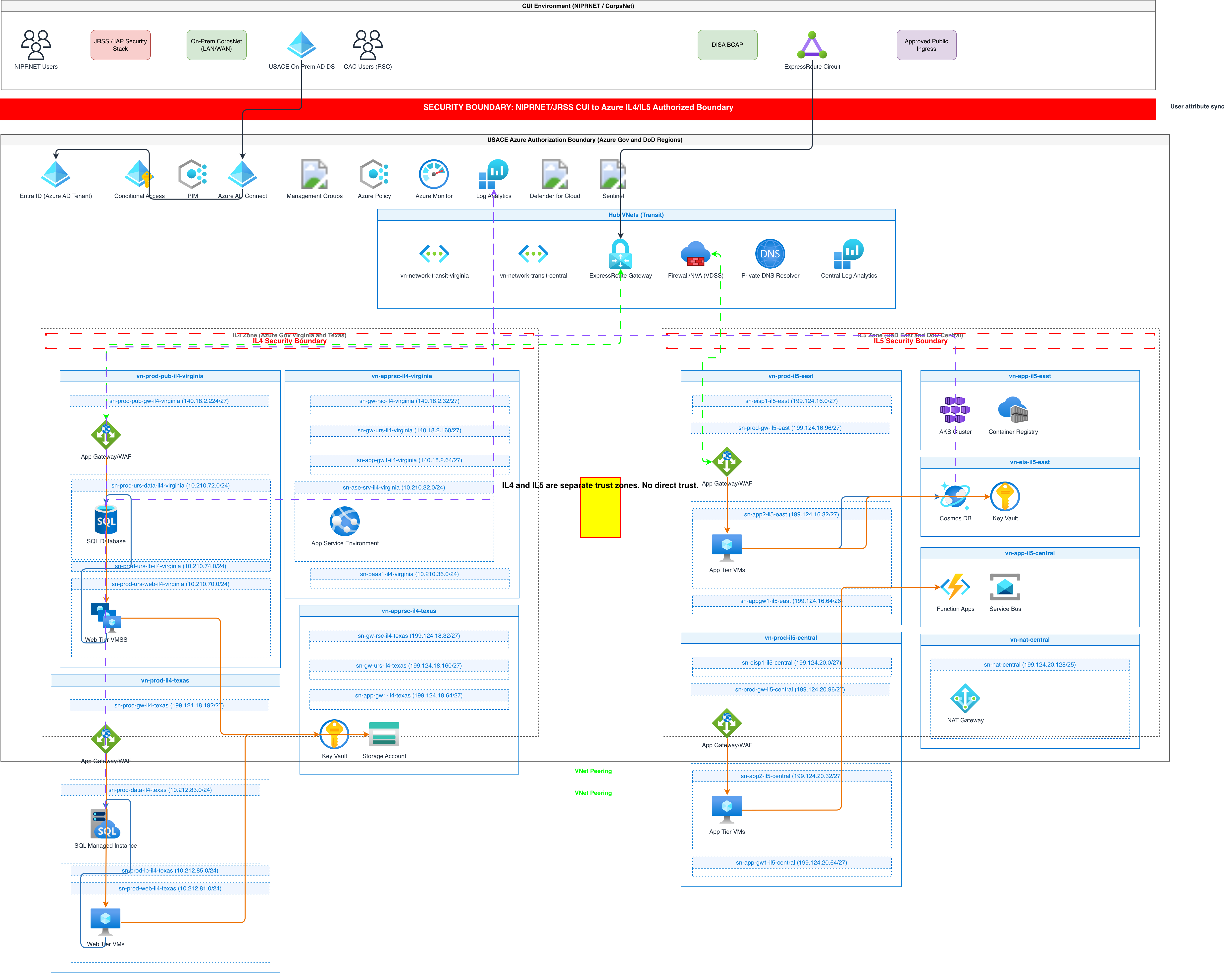
This AKS architecture diagram generator converts plain-text descriptions of your Azure Kubernetes Service clusters into Draw.io diagrams with node pools, networking, ingress controllers, and monitoring. Describe a setup like 'AKS cluster with a system node pool of 3 Standard_D4s_v5 nodes and a user node pool of 5 Standard_D8s_v5 nodes using Azure CNI with dynamic IP allocation, Application Gateway Ingress Controller with WAF v2, and Azure Key Vault CSI driver for secret injection.' The AI maps each component to its official Azure or CNCF icon, draws VNet integration boundaries, and shows pod-level networking with CNI subnet allocation. Architecture warnings flag clusters without multiple node pools (WARN-01) and missing network policies (WARN-04). Every element snaps to a 10px grid. Native .drawio output.
What Is an AKS Architecture Diagram?
An AKS architecture diagram maps the components of an Azure Kubernetes Service cluster: the control plane (managed by Microsoft), system and user node pools, VNet integration, ingress controllers, service mesh, secrets management, autoscaling configuration, and monitoring. AKS has Azure-specific constructs that generic Kubernetes diagrams miss. The control plane is fully managed. Node pools map to Azure VM Scale Sets with specific SKUs. Azure CNI assigns pod IPs directly from VNet subnets, unlike kubenet's overlay. Application Gateway Ingress Controller (AGIC) ties Azure Application Gateway with WAF v2 directly to Kubernetes Ingress resources. The Azure Key Vault CSI driver mounts secrets as volumes without storing them in etcd. Diagrams.so understands these AKS-specific constructs. Describe 'system node pool with 3 Standard_D4s_v5 nodes in snet-aks-system, user node pool with spot instances for batch workloads' and the AI draws two distinct node pool boundaries within the VNet subnet, labeled with VM SKU, node count, and autoscaler range. AGIC appears at the cluster edge connected to Application Gateway with WAF policy annotations. Pod identity shows as a managed identity connector from workloads to Key Vault and Storage. KEDA ScaledObjects attach to deployments with event source labels (Azure Service Bus queue depth, Event Hubs partition lag). Azure Monitor Container Insights connects to the Log Analytics workspace with collection rule annotations. RULE-02 enforces official Azure icons for AKS, Application Gateway, Key Vault, and Azure Monitor. RULE-06 groups resources by namespace. WARN-01 flags single-node system pools. WARN-04 detects missing network policies between namespaces. WARN-02 catches AGIC without WAF policy enabled. VLM visual validation identifies overlapping pod labels in dense clusters.
Key components
- System node pool (Standard_D4s_v5, taint CriticalAddonsOnly) and user node pools with VM SKU, count, and autoscaler min/max labels
- Azure CNI networking with subnet CIDR allocation, pod IP assignment, and Azure CNI Overlay option for large clusters
- Application Gateway Ingress Controller (AGIC) with WAF v2 policy, SSL termination, and path-based routing rules
- Azure Key Vault CSI driver with SecretProviderClass annotations mounting secrets as volumes in pods
- KEDA ScaledObjects with event source triggers (Service Bus queue length, Event Hubs checkpoint lag, Prometheus metrics)
- Azure Monitor Container Insights with Log Analytics workspace connection and data collection rule annotations
- Workload Identity (AAD pod identity v2) showing managed identity federation from Kubernetes service accounts to Azure resources
- Namespace boundaries with NetworkPolicy rules restricting inter-namespace traffic on specific ports
How to generate with AI
- 1
Describe your AKS cluster architecture
Write your AKS configuration in plain English with specific SKUs, networking, and add-ons. For example: 'AKS cluster aks-prod-eastus2 in VNet vnet-spoke-01 (10.1.0.0/16). System node pool: 3 Standard_D4s_v5 nodes in snet-aks-system (10.1.0.0/24), autoscaler min 3 max 5. User node pool: 5 Standard_D8s_v5 nodes in snet-aks-user (10.1.1.0/23), autoscaler min 3 max 20. Azure CNI with dynamic IP allocation. AGIC with Application Gateway WAF v2 in snet-appgw (10.1.4.0/24). Namespaces: app-frontend (3 replicas), app-backend (5 replicas with KEDA scaling on Service Bus queue), data (PostgreSQL Flexible Server via Private Link). Key Vault CSI driver injecting secrets from kv-prod-eastus2.'
- 2
Select architecture type and Azure provider
Choose 'Architecture' as the diagram type and 'Azure' as the cloud provider. Diagrams.so loads official Azure icons for AKS, Application Gateway, Key Vault, Azure Monitor, and VNet constructs, plus CNCF icons for Kubernetes resources like Deployments and Services. Enable opinionated mode to enforce VNet boundary nesting and ingress-to-backend left-to-right flow per RULE-05.
- 3
Generate and review
Click generate. The AI produces .drawio XML with the AKS cluster inside its VNet subnet, node pool boundaries labeled with SKUs, AGIC connected to Application Gateway, namespace containers with workloads, and KEDA/HPA annotations. Architecture warnings flag single-node system pools (WARN-01), missing WAF on AGIC (WARN-02), and namespaces without network policies (WARN-04). VLM visual validation catches overlapping pod labels. Download as .drawio or export to PNG/SVG.
Example prompt
AKS production architecture in East US 2. VNet vnet-spoke-aks (10.1.0.0/16) peered to hub VNet with Azure Firewall. AKS cluster aks-prod-eastus2 with Kubernetes 1.29. System node pool: 3 Standard_D4s_v5, snet-aks-system (10.1.0.0/24), taint CriticalAddonsOnly=true:NoSchedule, autoscaler min 3 max 5. User node pool compute: 5 Standard_D8s_v5, snet-aks-workload (10.1.1.0/23), autoscaler min 3 max 30. User node pool gpu: 2 Standard_NC24ads_A100_v4, snet-aks-workload, taint gpu=true:NoSchedule, for ML inference. Azure CNI with dynamic IP allocation. Application Gateway WAF v2 in snet-appgw (10.1.4.0/24) as AGIC with path-based routing: /api to backend-svc, /app to frontend-svc, /ml to inference-svc. Namespaces: app-frontend (React app, 3 replicas, HPA target 70% CPU), app-backend (.NET 8 API, 5 replicas, KEDA scaled on Azure Service Bus queue orders-queue depth > 10), ml-inference (TorchServe, 2 replicas on GPU node pool). Azure Key Vault kv-prod-eastus2 with CSI driver SecretProviderClass injecting DB connection strings and API keys. Workload Identity federation: app-backend service account federated to managed identity with Storage Blob Data Contributor on storage account. Azure Monitor Container Insights with Log Analytics workspace law-prod-eastus2, Prometheus metrics via Azure Managed Grafana. Network policies: app-frontend can reach app-backend on 8080, app-backend can reach PostgreSQL Flexible Server via Private Link on 5432, deny all other inter-namespace traffic.
Example diagrams from the gallery


AKS vs EKS vs GKE - Managed Kubernetes Architecture Compared
All three managed Kubernetes services abstract the control plane, but they differ in networking models, node management, ingress options, and cloud-native integrations. These architectural differences change how cluster diagrams are structured and what components appear.
| Feature | AKS | EKS | GKE |
|---|---|---|---|
| Networking model | Azure CNI assigns VNet IPs directly to pods; Azure CNI Overlay for large clusters; kubenet as legacy option with UDR routes | Amazon VPC CNI assigns ENI secondary IPs to pods; prefix delegation for higher pod density; Calico for network policies | VPC-native with alias IP ranges; GKE Dataplane V2 (Cilium-based eBPF) for networking and network policy enforcement |
| Ingress controller | AGIC ties Application Gateway WAF v2 directly to Ingress resources; nginx and Istio as alternatives; managed AGIC add-on | AWS Load Balancer Controller creates ALB per Ingress or NLB per Service; target group binding for pod-level routing | GKE Ingress Controller provisions Cloud Load Balancer with Cloud Armor WAF; Gateway API for multi-cluster routing |
| Secrets management | Azure Key Vault CSI driver mounts secrets as volumes; Workload Identity federates service accounts to managed identities | AWS Secrets Manager CSI driver; IRSA (IAM Roles for Service Accounts) maps pods to IAM roles via OIDC | Secret Manager CSI driver; Workload Identity federates KSA to Google service accounts; Config Connector for declarative secrets |
| Autoscaling | Cluster autoscaler per node pool; HPA and VPA; KEDA for event-driven scaling from Service Bus, Event Hubs, Prometheus | Karpenter for node provisioning; Cluster Autoscaler as alternative; HPA and VPA; KEDA supported but not pre-integrated | Node auto-provisioning creates node pools on demand; Cluster Autoscaler; HPA, VPA, and Multidimensional Pod Autoscaler |
| Monitoring | Azure Monitor Container Insights with Log Analytics; Azure Managed Prometheus and Grafana; diagnostic settings for control plane | CloudWatch Container Insights; Amazon Managed Prometheus and Grafana; control plane logging to CloudWatch Logs | Cloud Logging and Cloud Monitoring with GKE dashboard; Google Managed Prometheus; GKE Autopilot has built-in telemetry |
| Diagram layout | VNet boundary containing AKS subnet; node pools as bounded regions; AGIC at edge connecting to Application Gateway | VPC with public/private subnets per AZ; node groups as AZ-scoped blocks; ALB Controller at the VPC edge | VPC with regional subnet; node pools as flat groups; Cloud Load Balancer external to VPC boundary |
When to use this pattern
Use an AKS architecture diagram when documenting the internal structure of an Azure Kubernetes Service cluster for platform engineering teams, capacity planning, or Well-Architected Framework reviews. It's the right choice when you need to show node pool sizing, CNI networking with subnet allocation, AGIC ingress routing, and KEDA autoscaling configuration. If you need to document the broader Azure environment around the cluster (hub-spoke VNet, Azure Firewall, ExpressRoute), pair it with an Azure networking diagram. If your focus is on the CI/CD pipeline that deploys to AKS rather than the cluster itself, use an Azure DevOps pipeline diagram. For generic Kubernetes patterns without Azure-specific constructs, a Kubernetes diagram with CNCF icons fits better.
Frequently asked questions
Does the AKS architecture diagram generator show node pool details?
Yes. This AKS architecture diagram generator renders each node pool as a labeled boundary with VM SKU (Standard_D4s_v5), node count, autoscaler range (min 3, max 20), and taints. System and user node pools appear as distinct regions within the AKS cluster. GPU node pools show the accelerator SKU and scheduling taints.
How is Azure CNI networking represented?
Azure CNI networking shows pods receiving IP addresses directly from the VNet subnet. The diagram labels the subnet CIDR range and shows pod IPs within that range. For Azure CNI Overlay, the AI draws the overlay network as a separate address space inside the node pool boundary. Subnet capacity annotations help with IP planning.
Can I include KEDA autoscaling in the diagram?
Yes. Describe KEDA ScaledObjects with their event sources: 'backend deployment scaled by Azure Service Bus queue depth greater than 10.' The AI attaches a KEDA trigger annotation to the target deployment showing the event source, threshold, and min/max replica count. Multiple triggers on a single deployment are supported.
What architecture warnings apply to AKS diagrams?
WARN-01 flags system node pools with fewer than 3 nodes or user pools without autoscaler enabled. WARN-02 catches AGIC without WAF v2 policy enabled on the Application Gateway. WARN-04 detects namespaces missing NetworkPolicy definitions allowing unrestricted inter-namespace traffic. Warnings are non-blocking annotations.
Can the diagram show Workload Identity federation?
Yes. Describe which Kubernetes service accounts federate to Azure managed identities. The AI draws federation arrows from the service account in its namespace to the managed identity, then shows IAM role assignments to target resources like Key Vault, Storage, or Azure SQL. Each arrow is labeled with the assigned role.
Related diagram generators
Generate Kubernetes Diagrams from Text with AI
Describe your Kubernetes cluster in plain English. Get a valid Draw.io diagram with CNCF icons, namespace boundaries, deployments, services, and ingress controllers.
Generate Azure Architecture Diagrams from Text with AI
Describe your Azure infrastructure in plain English. Get a valid Draw.io diagram with official Azure icons, VNet boundaries, resource groups, and NSG rules.
Generate Azure networking diagrams from text
Describe your Azure network topology in plain English. Get a valid Draw.io diagram with hub-spoke VNets, Azure Firewall rules, NSG flows, and Private Link endpoints.
Generate Microservices Architecture Diagrams from Text
Describe your service boundaries in plain English. Get a valid Draw.io diagram with API gateways, message brokers, database-per-service patterns, and service mesh routing.