How to Create Azure Architecture Diagrams with AI
Azure has over 600 services, and diagramming them correctly requires the right icon set, proper grouping by resource group and subscription, and consistent layout. This tutorial walks through real prompts for landing zones, AKS clusters, data platforms, and security architectures you can use in Diagrams.so today.
Azure icon set: what it includes and why it matters for architecture reviews
Microsoft publishes an official Azure architecture icon set containing over 1,000 SVG icons organized by service category. These icons follow a specific visual language: blue outlines for compute, green for networking, purple for databases, orange for AI services. When your diagram uses official icons, reviewers instantly recognize services without reading labels. When you use generic boxes or outdated icons, every review meeting starts with five minutes of "what does this rectangle mean?" confusion. Diagrams.so includes the full Azure icon library as one of its 30+ icon sets. When you select Azure as your cloud provider, the AI maps service names in your prompt to the correct official icons automatically. Write "Azure Front Door" and you get the Front Door icon, not a generic CDN box. Write "Azure Cosmos DB" and you get the Cosmos DB icon with its distinctive multi-model symbol. This follows RULE-02: use official cloud provider icons. The icon set matters beyond aesthetics. Azure Well-Architected Framework reviews expect diagrams that use official iconography. Internal architecture boards at enterprises reject diagrams with inconsistent or unofficial visuals. If you're producing diagrams for compliance documentation, SOC 2 auditors expect standardized notation. Microsoft organizes their icons into categories: compute, networking, databases, storage, AI + ML, analytics, integration, security, identity, management, DevOps, and IoT. Each category uses a distinct color accent. Diagrams.so preserves these color conventions in the generated XML, so the exported .drawio file matches what you'd get from the official Visio stencils. The difference is you don't need Visio. The .drawio format opens in Draw.io, Confluence, VS Code, or any editor that reads mxGraphModel XML. One common problem: Microsoft updates their icon set roughly twice a year, and old icons get deprecated. The Azure Kubernetes Service icon changed between 2023 and 2024. App Service got a visual refresh. If your team maintains a local icon library, it drifts. Using Diagrams.so means the icon set stays current without manual updates to your stencil files.
Diagramming Azure landing zones with management groups and hub-spoke topology
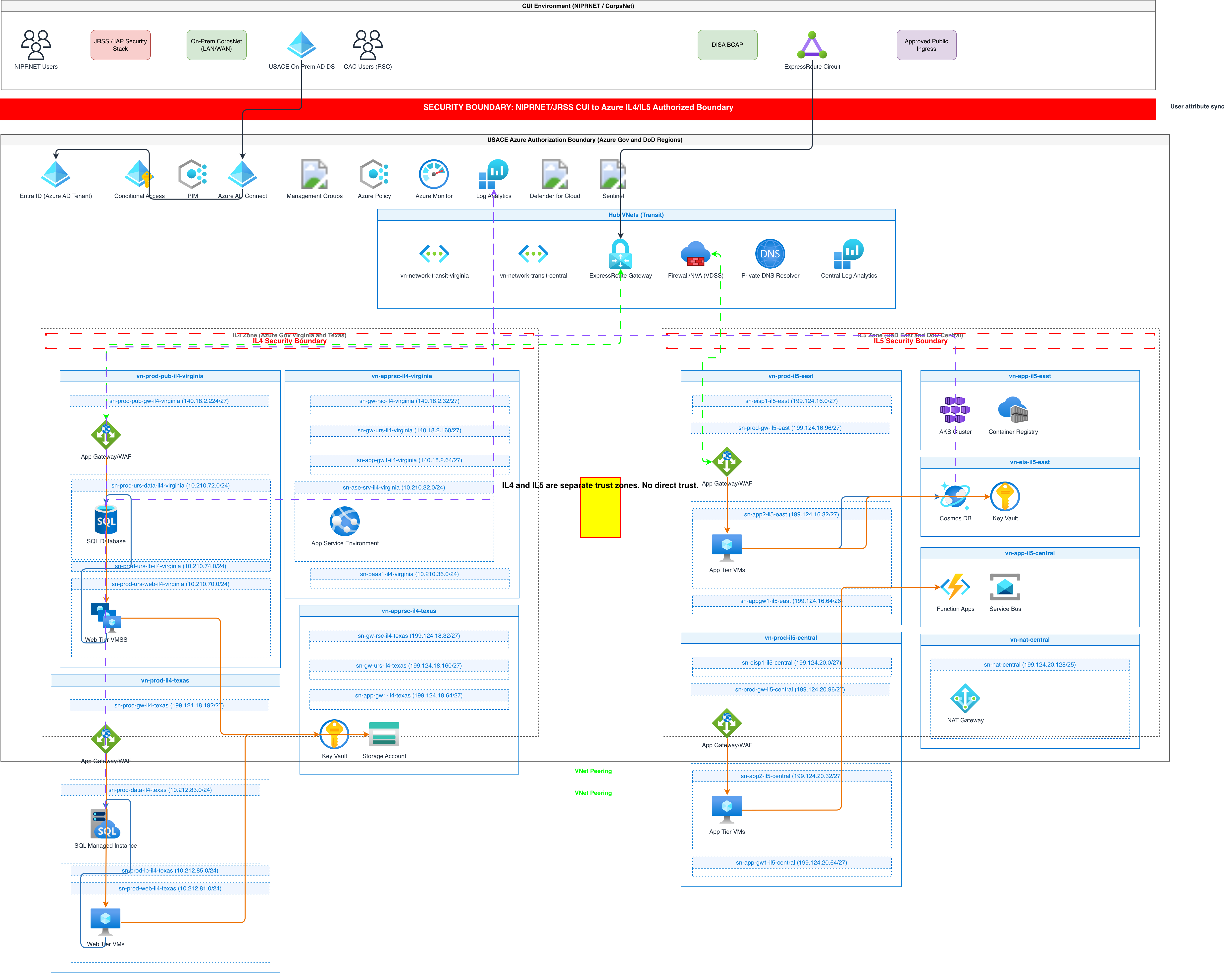
Azure landing zones define the subscription hierarchy, network topology, and governance controls that every workload sits on top of. Diagramming a landing zone correctly means showing management groups, subscriptions, hub-spoke network topology, and policy assignments. Most teams skip this because manually drawing a management group hierarchy with nested subscriptions in Draw.io takes 30+ minutes. Here's a prompt that generates a complete landing zone diagram: "Azure landing zone architecture with Enterprise-Scale structure. Root management group at the top, with child management groups: Platform (containing Identity, Management, and Connectivity subscriptions), Landing Zones (containing Corp and Online management groups, each with two workload subscriptions), Decommissioned, and Sandbox. Hub-spoke network topology: Connectivity subscription contains a hub VNet with Azure Firewall, ExpressRoute Gateway connecting to on-premises, and VPN Gateway for remote access. Two spoke VNets peered to the hub, one for Corp workload subscription containing three-tier app, one for Online workload subscription containing public-facing web app behind Azure Front Door. Show Azure Policy assignments at the Landing Zones management group level. Include Microsoft Defender for Cloud at the root management group." This generates a diagram with the management group tree at the top, flowing down into the network topology below. The hub VNet sits in the center with Azure Firewall, ExpressRoute Gateway, and VPN Gateway. Spoke VNets branch left and right. Each spoke contains its workload components inside subscription boundaries. Policy icons attach to the Landing Zones management group. Defender for Cloud spans the root. The AI groups components by subscription boundary, which is critical for Azure diagrams. Unlike AWS where the VPC is the primary boundary, Azure diagrams need to show both the subscription container and the VNet container inside it. Diagrams.so nests these correctly: management group contains subscriptions, subscriptions contain resource groups, resource groups contain resources. The hierarchy renders as nested rounded rectangles with distinct border colors. Architecture warnings are particularly useful here. WARN-01 fires if your hub VNet only exists in one region. WARN-04 fires if workload subscriptions lack NSG boundaries. These catch governance gaps that landing zone reviews specifically look for.
AKS cluster architecture: nodes, networking, and identity integration
Azure Kubernetes Service diagrams need to show the cluster boundary, node pools, networking model, and integration with Azure AD and Azure Container Registry. The common mistake is drawing AKS as a single box with arrows going in and out. That tells reviewers nothing about the actual deployment topology. Use this prompt to generate a detailed AKS architecture: "AKS cluster architecture in a dedicated VNet with Azure CNI networking. System node pool with 3 nodes running CoreDNS and kube-proxy. User node pool with autoscaling from 3 to 10 nodes running application workloads. NGINX Ingress Controller exposed via Azure Load Balancer with a public IP. Application Gateway Ingress Controller as an alternative entry point with WAF v2 policy. Pod-managed identities connecting to Azure Key Vault for secrets, Azure Cosmos DB for data, and Azure Service Bus for messaging. Azure Container Registry with private endpoint in the same VNet. Azure Monitor with Container Insights enabled for metrics and log collection. Azure AD integration for RBAC with Kubernetes cluster role bindings." The generated diagram shows the AKS cluster as a large boundary containing two node pool groups. The system node pool sits on the left with CoreDNS and kube-proxy icons. The user node pool sits on the right with multiple pod representations. Two ingress paths enter from the left: one through Azure Load Balancer to NGINX, another through Application Gateway with a WAF shield icon. On the right side, arrows exit the cluster boundary to Azure Key Vault, Cosmos DB, and Service Bus, each connected via pod-managed identity (shown as a small identity icon on the arrow). ACR connects via private endpoint, shown as a dotted-line connection staying inside the VNet boundary. Azure Monitor sits above the cluster with collection arrows pointing down. This level of detail matters because AKS reviews always ask about ingress strategy, secrets management, and container image source. A diagram that shows all three answers questions before they're asked. The pod-managed identity connections are especially important: they show that workloads authenticate to Azure services without storing credentials in the cluster. WARN-02 fires if you expose the Load Balancer without mentioning WAF, which is why the prompt includes the WAF v2 policy on Application Gateway.
Azure data platform: Synapse, Data Factory, and the modern analytics stack
Azure data platform diagrams have a specific flow: ingest, store, process, serve, visualize. Getting this left-to-right flow correct in a diagram means reviewers can trace data lineage from source to dashboard. Most manually drawn data platform diagrams end up as a tangled web because people add components wherever there's whitespace. Here's a prompt for a complete Azure data platform: "Azure modern data platform architecture. Data sources on the left: Azure SQL Database, Azure Cosmos DB, and external REST APIs. Azure Data Factory orchestrates all ingestion pipelines with managed VNet integration. Raw data lands in Azure Data Lake Storage Gen2 (ADLS) bronze layer. Azure Databricks workspace processes data from bronze to silver (cleaned) to gold (aggregated) medallion layers, all in ADLS. Azure Synapse Analytics serverless SQL pool queries the gold layer directly. Synapse dedicated SQL pool serves curated datasets. Power BI connects to Synapse dedicated pool for executive dashboards. Azure Purview scans all data assets for cataloging and lineage. Azure Key Vault stores all connection strings and service principal credentials. All components inside a single resource group in a hub-spoke VNet with private endpoints." The generated diagram flows left to right: three data source icons on the far left, arrows into Data Factory in the center-left, arrows into ADLS with three labeled containers (bronze, silver, gold) in the center. Databricks sits above ADLS with bidirectional arrows showing the transformation flow between layers. Synapse Analytics appears center-right with two pool types. Power BI sits on the far right with a dashboard icon. Purview spans the bottom with scanning arrows pointing up to each data asset. Key Vault sits in the top corner with dotted-line arrows to every service that needs credentials. The medallion architecture (bronze/silver/gold) is a pattern that Databricks popularized, and Azure adopted it as a recommended data architecture. Showing the three layers as distinct containers inside ADLS makes the data transformation stages visible. Without this, the diagram just shows "Data Factory points to storage" which tells you nothing about the processing pipeline. Private endpoints deserve their own visual treatment. The prompt specifies private endpoints, and the AI renders them as small lock icons on the connections that stay within the VNet boundary. This is critical for data platform reviews where data exfiltration risk is a primary concern. WARN-04 fires if the data platform components lack network boundaries, pushing you to add the VNet and private endpoint details.
Visualizing Azure security architecture: NSGs, Firewall, and Key Vault integration
Security architecture diagrams on Azure need to show three layers: network security (NSGs, Azure Firewall, DDoS Protection), identity security (Azure AD, Managed Identity, Conditional Access), and data security (Key Vault, encryption at rest, TDE). Most diagrams only show network security because it maps naturally to visual boundaries. Identity and data security are harder to draw but equally important for compliance reviews. Use this prompt for a security-focused Azure diagram: "Azure security architecture for a regulated financial application. Internet traffic enters through Azure DDoS Protection Standard, then Azure Front Door with WAF policy enforcing OWASP 3.2 rules. Traffic routes to Application Gateway in a DMZ subnet with NSG allowing only HTTPS from Front Door service tag. Application Gateway forwards to Azure App Service Environment v3 in an isolated subnet with NSG blocking all internet-originated traffic. App Service uses managed identity to access Azure Key Vault for TLS certificates and database connection strings. Azure SQL Database with TDE enabled and Azure AD-only authentication, no SQL auth. Microsoft Defender for SQL monitors query patterns. Azure Private Link connects App Service to SQL Database with no public endpoint. Microsoft Entra Conditional Access requires compliant devices and MFA for admin portal access. Microsoft Sentinel collects logs from all components through diagnostic settings to Log Analytics workspace. Show Azure Policy assignments enforcing encryption and network isolation at the subscription level." The generated diagram arranges security layers from left (internet edge) to right (data tier). DDoS Protection and Front Door appear as the outermost shield. The DMZ subnet contains Application Gateway with NSG rules shown as a small table on the boundary. The isolated subnet contains App Service Environment with a tighter NSG. Key Vault connects via managed identity, shown as an identity arrow rather than a network arrow, which is an important distinction. SQL Database sits in its own subnet with Private Link connection from App Service, and TDE is shown as an encryption badge on the database icon. Microsoft Sentinel and Log Analytics span the bottom of the diagram with collection arrows pointing up to every component. This shows the security monitoring coverage and makes it immediately visible if any component lacks logging. Azure Policy appears at the subscription boundary level with governance icons. Diagrams.so architecture warnings catch specific security gaps here. WARN-02 fires if any component faces the internet without WAF. WARN-04 fires if subnets lack NSG definitions. The prompt above addresses both, but if you simplify the prompt, the warnings remind you what's missing. This is particularly valuable for PCI DSS and SOC 2 compliance documentation where every network boundary and encryption configuration must be visible in the architecture diagram.
Common Azure diagram mistakes and how to fix them with better prompts
After generating hundreds of Azure architecture diagrams, patterns emerge in what goes wrong and how to fix it. These mistakes aren't bugs in the AI. They're gaps in the prompt that produce technically valid but architecturally misleading diagrams. Mistake 1: Flat diagrams without subscription or resource group boundaries. If your prompt says "App Service connects to SQL Database connects to Redis Cache," you get three icons with arrows. There's no context about where these resources live. Fix: always specify the subscription, resource group, and VNet in your prompt. "Inside the Production subscription, web-rg resource group, in the app-vnet VNet" gives the AI the container hierarchy it needs to draw proper boundaries. Mistake 2: Mixing abstraction levels. A prompt that mentions "Azure region" and "container port 8080" in the same sentence forces the AI to fit infrastructure-level and application-level details into one diagram. Fix: generate separate diagrams for each abstraction level. One diagram for the subscription and network topology. Another for the application components inside the AKS cluster. A third for the CI/CD pipeline. Link them with consistent naming. Mistake 3: Missing the identity layer. Azure architectures rely heavily on Azure AD (now Microsoft Entra ID) for authentication between services. Prompts that only describe network connections miss the identity connections. Fix: explicitly mention how each service authenticates. "App Service uses managed identity to access Key Vault" adds an identity arrow that reviewers expect to see. Mistake 4: Using generic names instead of Azure service names. "A load balancer" could mean Azure Load Balancer, Application Gateway, Azure Front Door, or Traffic Manager. Each has a different icon and different architectural implications. Fix: use the exact Azure service name. WARN-05 fires on ambiguous component names, guiding you toward specificity. Mistake 5: Ignoring paired regions and availability zones. Azure's resiliency model depends on AZ distribution within a region and paired region failover for DR. Prompts that don't mention these produce single-point-of-failure diagrams. Fix: specify availability zones for compute and storage, and mention the DR region if your architecture includes one. "Primary in East US with AZ 1, 2, 3. DR in West US with passive replicas" gives the AI enough to draw a proper multi-region layout. Mistake 6: Omitting hybrid connectivity. Many Azure deployments connect to on-premises infrastructure via ExpressRoute or Site-to-Site VPN. Leaving this out of the diagram makes it look like a greenfield cloud deployment when it's actually hybrid. Fix: include the connectivity mechanism and on-premises components in your prompt, even if they're drawn as a simple "On-premises data center" box with an ExpressRoute connection.
Related diagrams from the gallery


Try these diagram generators
Generate Azure Architecture Diagrams from Text with AI
Describe your Azure infrastructure in plain English. Get a valid Draw.io diagram with official Azure icons, VNet boundaries, resource groups, and NSG rules.
Generate Azure landing zone diagrams from text
Describe your Azure management group hierarchy, hub-spoke network topology, and policy assignments in plain English. Get a valid Draw.io diagram with official Azure icons.
Generate AKS Architecture Diagrams from Text with AI
Describe your Azure Kubernetes Service cluster in plain English. Get a valid Draw.io diagram with node pools, Azure CNI networking, AGIC ingress, and KEDA autoscaling.