Starlink SD-WAN Failover Architecture (FortiGate)
About This Architecture
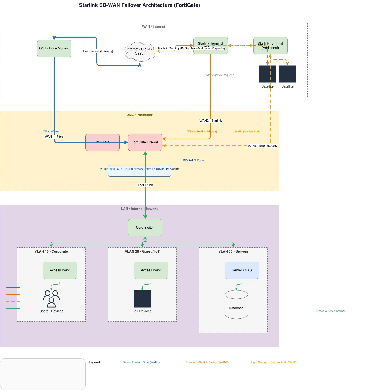
Starlink SD-WAN failover architecture with FortiGate firewall orchestrates three WAN links—primary fibre (WAN1), Starlink primary satellite (WAN2), and Starlink additional satellite (WAN3)—to ensure continuous connectivity and load balancing. Traffic flows from Internet/Cloud/SaaS through ONT fibre modem and dual Starlink terminals into the FortiGate firewall, which applies WAF/IPS rules and routes packets across SD-WAN zones based on performance SLA thresholds. Internal network segments—VLAN 10 (Corporate), VLAN 20 (Guest/IoT), VLAN 30 (Servers)—connect via core switch with dedicated access points and server infrastructure. This architecture eliminates single points of failure by automatically failover from fibre to satellite when primary WAN degrades, critical for remote sites and disaster recovery scenarios. Fork this diagram on Diagrams.so to customize WAN policies, add additional VLANs, or integrate with your FortiGate management console templates.
People also ask
How do I design a resilient SD-WAN failover architecture using Starlink satellite as backup with FortiGate firewall?
This diagram shows a three-WAN architecture where FortiGate firewall manages primary fibre (WAN1) and dual Starlink satellite links (WAN2/WAN3) with automatic failover based on performance SLA rules. Internal traffic is segmented across three VLANs (Corporate, Guest/IoT, Servers) with WAF/IPS protection, ensuring continuous connectivity even when primary fibre fails.
- Domain:
- Networking
- Audience:
- Network architects designing resilient SD-WAN failover solutions with satellite backup
Generated by Diagrams.so — AI architecture diagram generator with native Draw.io output. Fork this diagram, remix it, or download as .drawio, PNG, or SVG.