Saha Tesis Yerlesim - Kabin ve Altyapi Plani
About This Architecture
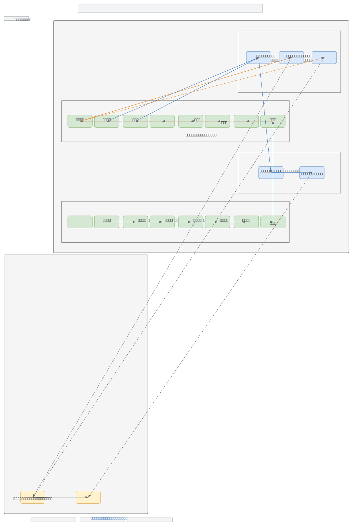
Field facility site layout plan integrating dual cabin line corridors (north AS8–AS18 and south AS9–AS16) with centralized infrastructure hub connecting transformer center, operations building, and concrete shelter. Cabin connections via fiber/cable and power distribution lines converge through support units (scale BS02, cabinet BS03) to the main facility area. This hierarchical topology ensures redundancy and load distribution across geographically separated monitoring or control stations. Fork this diagram on Diagrams.so to customize cabin positions, add utility specifications, or adapt for your site's geographic and operational constraints.
People also ask
How should I design a field facility layout with multiple distributed cabins connected to a centralized infrastructure hub?
This diagram shows a proven topology: dual cabin corridors (north AS8–AS18, south AS9–AS16) converge through a concrete shelter to a centralized hub containing transformer center, operations building, and support units. Fiber/cable and power lines distribute from the hub to each cabin station, enabling redundancy and scalable monitoring.
- Domain:
- Mechanical Engineering
- Audience:
- Site engineers and facility planners designing field infrastructure layouts with distributed cabin and utility connectio
Generated by Diagrams.so — AI architecture diagram generator with native Draw.io output. Fork this diagram, remix it, or download as .drawio, PNG, or SVG.