Poste Source 60/10 kV - Schema de Puissance
About This Architecture
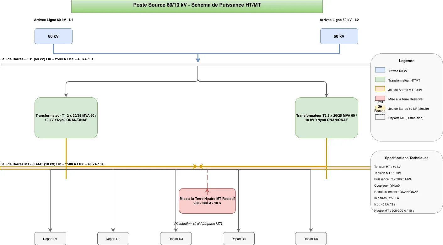
High-voltage substation single-line diagram showing a 60/10 kV step-down power station with dual incoming 60 kV lines feeding two independent 60 kV busbars (JB1 and JB2) rated 2500 A nominal and 40 kA short-circuit capacity. Two 20/25 MVA transformers with YNyn0 coupling and ONAN/ONAF cooling step voltage down to a 10 kV medium-voltage busbar (JB-MT) that distributes power to five outgoing feeders (D1–D5). A resistive neutral earthing system (200–300 A / 10 s) on the medium-voltage side ensures safe fault clearance and overvoltage control. This architecture demonstrates redundancy at both HV and MV levels, critical for reliable industrial and utility power delivery. Fork and customize this diagram on Diagrams.so to adapt specifications, add protection relays, or integrate SCADA monitoring points.
People also ask
What does a typical 60/10 kV substation single-line diagram look like with dual transformers and redundant busbars?
This diagram shows a step-down substation where two 60 kV incoming lines feed independent busbars (JB1, JB2) that supply two 20/25 MVA transformers stepping voltage to 10 kV. The medium-voltage busbar (JB-MT) then distributes power to five feeders with resistive neutral earthing for fault protection.
- Domain:
- Electrical Engineering
- Audience:
- electrical engineers designing high-voltage substations and power distribution networks
Generated by Diagrams.so — AI architecture diagram generator with native Draw.io output. Fork this diagram, remix it, or download as .drawio, PNG, or SVG.