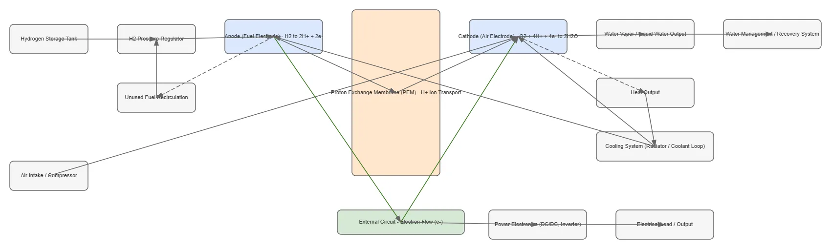
PEM Fuel Cell System Process Flow architecture diagram

About This Architecture

Proton Exchange Membrane (PEM) fuel cell system with hydrogen storage, pressure regulation, and electrochemical conversion to electrical power. Hydrogen flows through the anode where it oxidizes to protons and electrons, while compressed air enters the cathode for oxygen reduction, with protons transported across the PEM membrane. Electrons travel through an external circuit to power electronics that condition DC output for electrical loads, while water and heat byproducts are managed through recovery and cooling subsystems. This diagram illustrates the complete thermodynamic and electrochemical process chain essential for designing efficient, reliable fuel cell powertrains. Fork and customize this architecture on Diagrams.so to model your specific fuel cell stack, thermal management, or hydrogen supply requirements.

People also ask

How does a PEM fuel cell system convert hydrogen to electrical power and manage heat and water byproducts?

A PEM fuel cell oxidizes hydrogen at the anode into protons and electrons; protons cross the proton exchange membrane to the cathode where they react with oxygen to produce water, while electrons flow through an external circuit and power electronics to deliver electrical output. Heat and water vapor are managed through dedicated cooling and recovery systems, with unused fuel recirculated to maxim

PEM Fuel Cell System Process Flow

Autoadvancedfuel cellhydrogen energyPEMmechanical engineeringpower electronicsthermal management
Domain: Mechanical EngineeringAudience: mechanical engineers and fuel cell system designers
1 views0 favoritesPublic

Created by

July 30, 2026

Updated

August 8, 2026 at 11:41 PM

Type

others

Need a custom architecture diagram?

Describe your architecture in plain English and get a production-ready Draw.io diagram in seconds. Works for AWS, Azure, GCP, Kubernetes, and more.

Generate with AI

AI-generated. Verify before production use. Learn more

Report this diagram