OCI Hub-Spoke Network - uk-london-1
About This Architecture
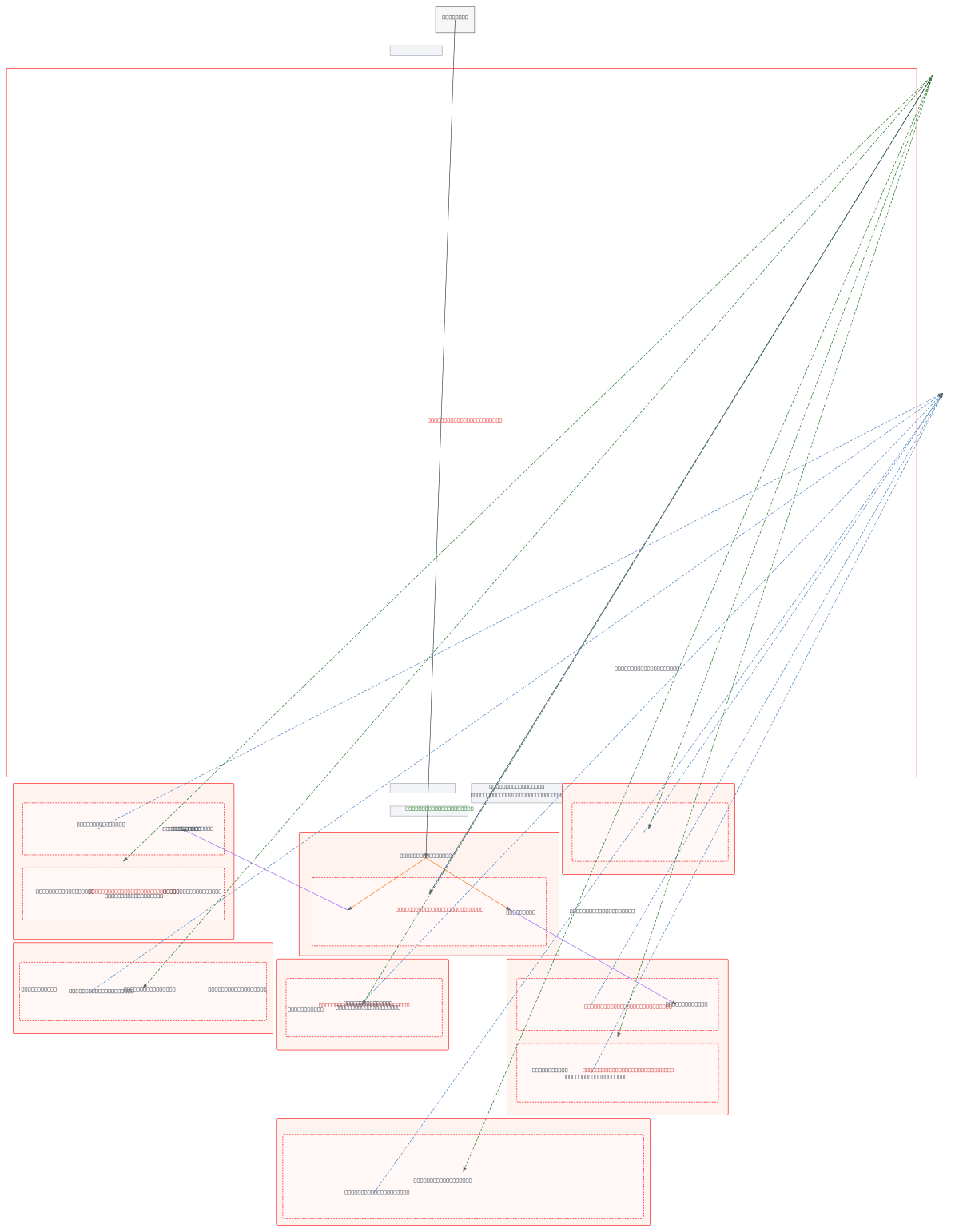
Hub-spoke network topology in OCI Region uk-london-1 with a central COMMON VCN (10.0.0.0/16) connected via Dynamic Routing Gateway to six spoke VCNs spanning PROD, EPM, PMO, DEMO, and customer workloads. Traffic flows through DRG route tables enforcing 0.0.0.0/0 spoke-to-hub and 10.1-6.0.0/16 hub-to-spoke routing, with NLBs in the hub distributing PROD and CUS traffic across compute instances and instance pools. Each spoke isolates workloads using private subnets, NAT gateways for egress, and Service Gateways for OCI Object Storage access, while the hub exposes public subnets with Internet Gateway for inbound connectivity and OpenVPN Access Servers in COMMON and CUS spokes. This architecture centralizes security controls, simplifies routing, and enables cost-efficient resource sharing while maintaining workload isolation across development, production, and customer environments. Fork this diagram on Diagrams.so to customize CIDR ranges, add additional spokes, or adapt routing policies for your multi-tenant OCI deployment. Consider adding Network Security Groups at the subnet level and implementing DRG route table filters for granular east-west traffic control.
People also ask
How do I design a hub-spoke network in OCI with multiple workload spokes and centralized routing?
This diagram shows a production hub-spoke topology using OCI's Dynamic Routing Gateway to connect a central COMMON VCN (hub) with six isolated spoke VCNs. DRG route tables enforce directional routing (0.0.0.0/0 spoke-to-hub, 10.1-6.0.0/16 hub-to-spoke), while NLBs in the hub distribute traffic and NAT/Service Gateways in spokes enable secure egress and OCI Object Storage access.
- Domain:
- Cloud Aws
- Audience:
- OCI cloud architects designing multi-workload hub-spoke networks
Generated by Diagrams.so — AI architecture diagram generator with native Draw.io output. Fork this diagram, remix it, or download as .drawio, PNG, or SVG.