OCI Dual-Region DRG Remote Peering - 12 VCNs
About This Architecture
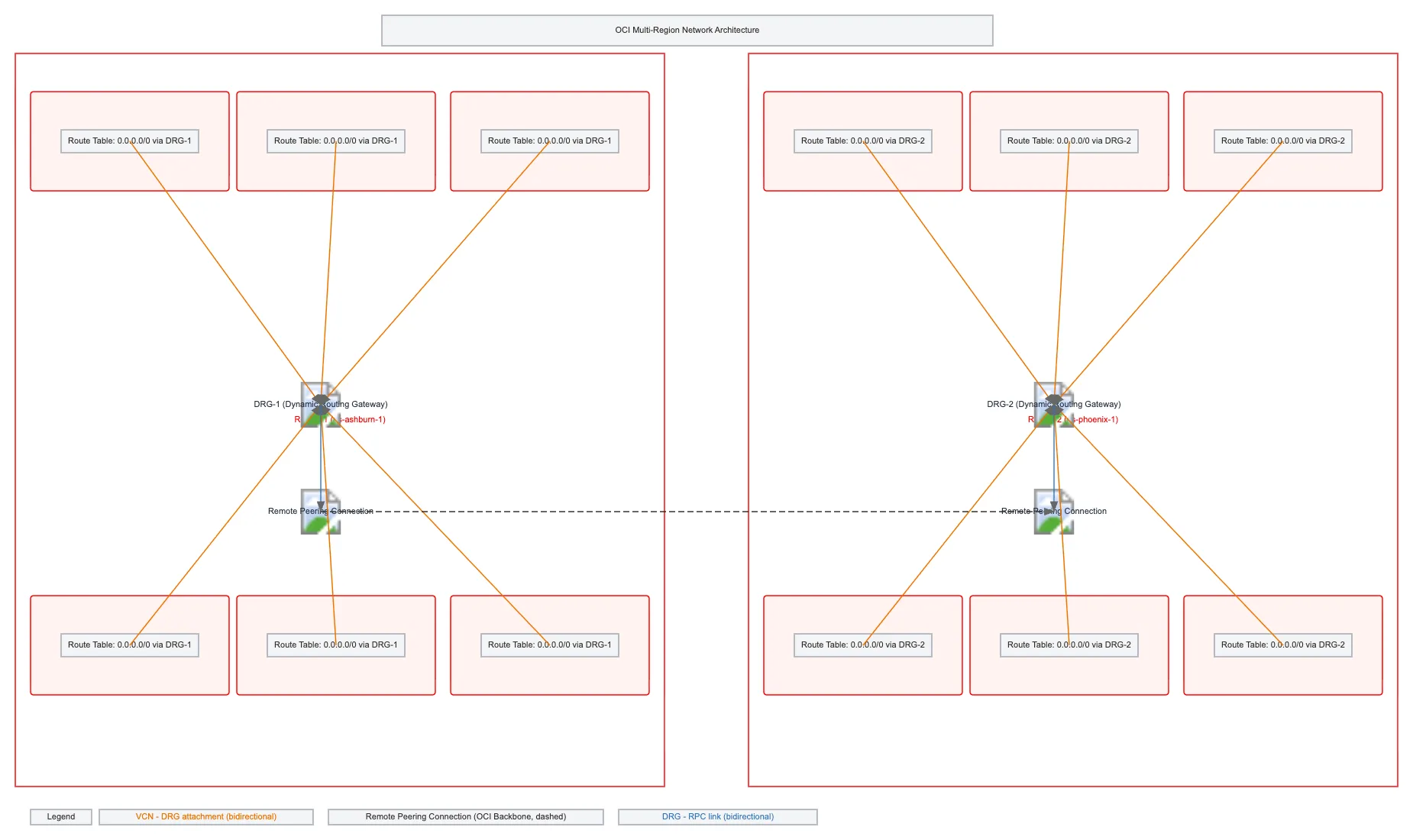
OCI dual-region architecture with 12 VCNs connected via Dynamic Routing Gateways and Remote Peering Connections across us-ashburn-1 and us-phoenix-1. Six VCNs in Region 1 (10.1.0.0/16 through 10.6.0.0/16) attach to DRG-1, while six VCNs in Region 2 (10.11.0.0/16 through 10.16.0.0/16) attach to DRG-2, with all traffic routed through their respective DRGs. The two DRGs connect via Remote Peering Connection over the OCI backbone, enabling seamless inter-region communication and centralized routing policy enforcement. This hub-and-spoke pattern with remote peering provides high availability, simplified network management, and disaster recovery capabilities across geographically distributed regions. Fork and customize this diagram on Diagrams.so to match your own VCN CIDR blocks, add security rules, or extend to additional regions.
People also ask
How do I connect multiple VCNs across two OCI regions using Dynamic Routing Gateways and Remote Peering?
This diagram shows a hub-and-spoke topology where six VCNs in Region 1 attach to DRG-1 and six VCNs in Region 2 attach to DRG-2. The two DRGs connect via Remote Peering Connection over the OCI backbone, enabling all VCNs to communicate across regions with centralized routing through their respective gateways.
- Domain:
- Cloud Oci
- Audience:
- OCI network architects designing multi-region disaster recovery and hub-and-spoke topologies
Generated by Diagrams.so — AI architecture diagram generator with native Draw.io output. Fork this diagram, remix it, or download as .drawio, PNG, or SVG.