Logical MPLS IPWAN Architecture
About This Architecture
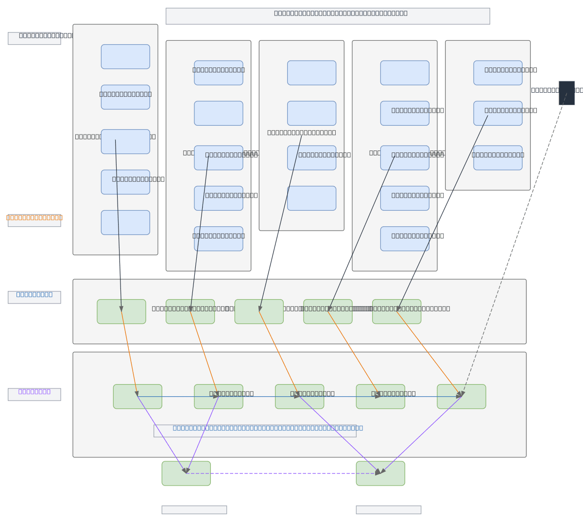
Enterprise MPLS/IPWAN architecture with hierarchical access aggregation across NBN TC4 and NBN-EE-H technologies, routing through PE and P routers with logical VRF separation per customer. Customer sites connect via tiered access nodes (100/40M, 50/20M, 50M, 100M, 200M links) to PE routers that form the provider core backbone. Dual head-end design with 4Gbps NBN-EE-H uplinks ensures redundancy and service isolation for multi-tenant environments. This architecture demonstrates carrier-grade MPLS best practices: traffic engineering, VRF-based customer isolation, and resilient dual-core topology. Fork this diagram on Diagrams.so to customize PE/P router counts, add QoS policies, or model failover scenarios. Optional mobile backup path provides additional resilience for critical customer sites.
People also ask
How do I design a scalable MPLS/IPWAN network with VRF separation and redundant head-ends?
This diagram shows a carrier-grade MPLS/IPWAN topology where customer sites connect via tiered NBN access nodes to PE routers, which aggregate traffic through P routers to dual head-ends with 4Gbps uplinks. Logical VRF separation isolates each customer's traffic, while PE-to-PE and head-end-to-head-end links provide redundancy and traffic engineering capabilities.
- Domain:
- Networking
- Audience:
- Network architects designing enterprise MPLS/IPWAN infrastructures
Generated by Diagrams.so — AI architecture diagram generator with native Draw.io output. Fork this diagram, remix it, or download as .drawio, PNG, or SVG.