Internet Fault Management System - L1 DFD
About This Architecture
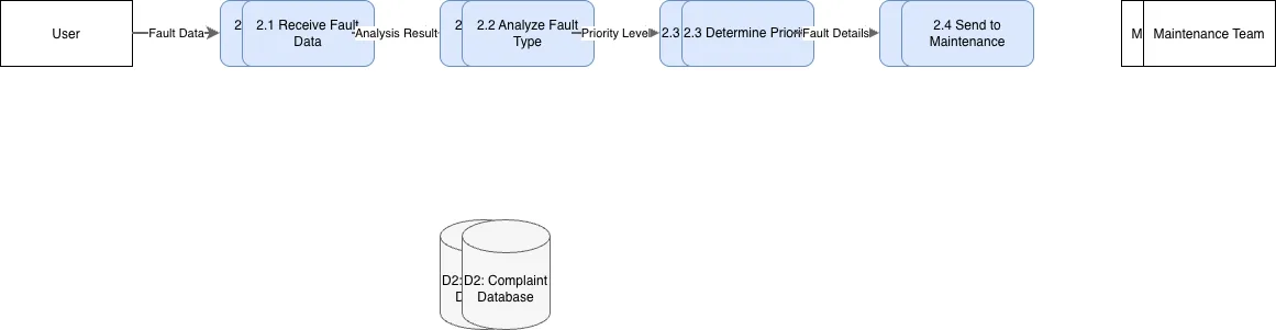
Level 1 Data Flow Diagram for an Internet Fault Management System capturing the complete lifecycle from fault report submission through maintenance execution and status updates. Users submit fault reports to process 1.0, which stores complaints in the Complaint Database and routes analysis to process 2.0, triggering maintenance assignment in process 3.0 and team dispatch. The Maintenance Team executes work and returns status via process 4.0, which updates both the User and Complaint Database with resolution details. This architecture demonstrates separation of concerns across fault intake, diagnosis, execution, and notification—essential for managing service disruptions at scale. Fork this diagram on Diagrams.so to customize processes, add escalation paths, or integrate with your incident management tools. The two-database design (User and Complaint) supports independent scaling of identity and fault tracking systems.
People also ask
How does a fault management system handle user complaints from submission through maintenance and status notification?
This Level 1 DFD illustrates a four-process workflow: users submit fault reports (1.0), which are analyzed (2.0) and routed to maintenance management (3.0), where teams execute repairs and return status updates (4.0) to both users and the complaint database. This design ensures clear separation between fault intake, diagnosis, execution, and communication.
- Domain:
- Software Architecture
- Audience:
- Business analysts and systems architects designing fault management and incident response workflows
Generated by Diagrams.so — AI architecture diagram generator with native Draw.io output. Fork this diagram, remix it, or download as .drawio, PNG, or SVG.