Inspection Robot System Architecture
About This Architecture
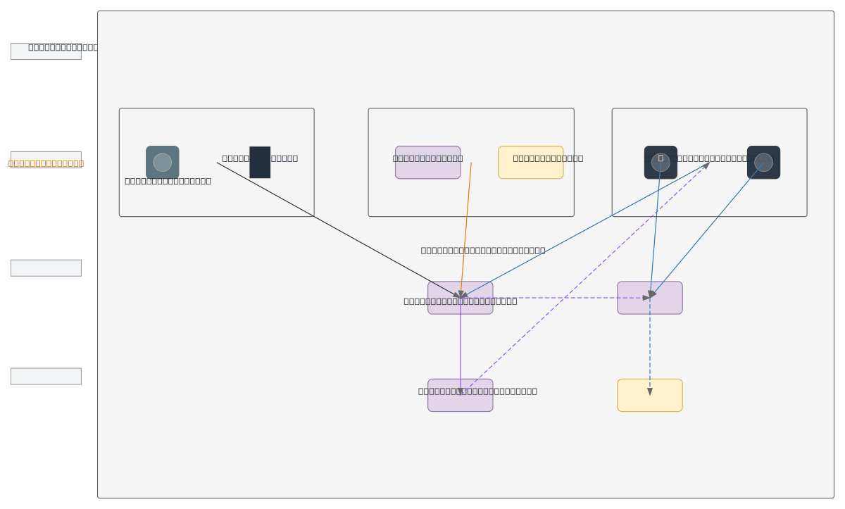
Inspection robot system architecture integrating modular input, motion, and imaging subsystems coordinated through a central system core. Input Control Module accepts keyboard and remote commands, Motion Control Module manages motor and speed regulation, and Image Acquisition Module captures color and depth imagery—all synchronized via Linkage Control Logic. This modular design enables real-time sensor fusion and autonomous camera triggering, critical for industrial inspection tasks requiring precision navigation and visual analysis. Fork and customize this diagram on Diagrams.so to adapt sensor types, add communication protocols, or extend the monitoring dashboard for your specific inspection application.
People also ask
How should I structure the control architecture for an inspection robot with multiple sensors and input methods?
This diagram shows a modular approach where a System Core coordinates three main subsystems: Input Control Module (keyboard/remote), Motion Control Module (motor/speed), and Image Acquisition Module (color/depth cameras). All subsystems feed into Linkage Control Logic, which synchronizes camera auto-start/stop with motion and processes sensor data to a monitoring dashboard.
- Domain:
- Mechanical Engineering
- Audience:
- Robotics engineers designing inspection robot control systems
Generated by Diagrams.so — AI architecture diagram generator with native Draw.io output. Fork this diagram, remix it, or download as .drawio, PNG, or SVG.