House HVAC and Plumbing - 3 Apartments
About This Architecture
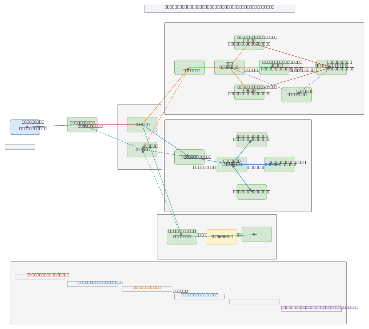
Integrated HVAC and plumbing system for a 3-apartment house using a Panasonic Aquarea T-CAP 12 kW air-to-water heat pump as the primary energy source. The heat pump feeds a buffer tank and hydraulic separator that distributes hot water through three independent circuits: domestic hot water (DHW) with three 200–300 L tanks and recirculation pump, fan coil cooling units for each apartment floor, and a swimming pool heat exchanger loop. Each circuit has its own circulation pump (P1, P2, P3) and manifold for independent flow control and temperature management. This architecture ensures reliable, zone-controlled comfort while optimizing energy efficiency across heating, cooling, and DHW demands. Fork this diagram on Diagrams.so to customize tank sizes, pump capacities, or add additional circuits for your specific multi-unit project. The modular design allows easy scaling to larger buildings or alternative heat sources.
People also ask
How do you design an HVAC and plumbing system for a multi-apartment house with separate heating, cooling, and hot water circuits?
This diagram shows a heat pump-driven architecture where a Panasonic Aquarea T-CAP 12 kW unit supplies a buffer tank that feeds three independent circuits: DHW with three storage tanks and recirculation, fan coil cooling for each apartment floor, and a swimming pool heat exchanger. Each circuit has its own circulation pump and manifold for zone control and efficiency.
- Domain:
- Mechanical Engineering
- Audience:
- HVAC engineers and mechanical designers planning multi-unit residential heating, cooling, and domestic hot water systems
Generated by Diagrams.so — AI architecture diagram generator with native Draw.io output. Fork this diagram, remix it, or download as .drawio, PNG, or SVG.