AWS Tokyo Single-AZ Web App Architecture
About This Architecture
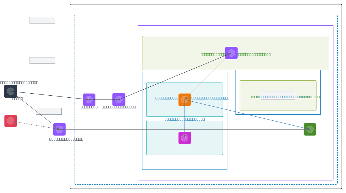
Single-AZ web application architecture in AWS Tokyo (ap-northeast-1) using Route 53 DNS, Application Load Balancer across public subnets, EC2 t3.small instances in private app tier, RDS MySQL for data persistence, and S3 for static assets. Traffic flows from users through Route 53 and Internet Gateway to the ALB, which distributes requests to EC2 instances that query RDS and fetch objects from S3. This pattern optimizes for cost and latency in the Tokyo region while maintaining separation of concerns across public, application, and data subnets. Fork this diagram on Diagrams.so to customize instance types, add multi-AZ redundancy, or adjust CIDR blocks for your workload. Consider upgrading to multi-AZ deployment for production workloads requiring higher availability and automatic failover.
People also ask
How do I design a cost-optimized web application architecture in AWS Tokyo region with load balancing and database persistence?
This diagram shows a single-AZ web app in AWS Tokyo (ap-northeast-1) where Route 53 routes traffic through an Internet Gateway to an Application Load Balancer, which distributes requests to EC2 t3.small instances in a private subnet. EC2 instances connect to RDS MySQL for data and S3 for static assets, optimizing for regional latency and cost.
- Domain:
- Cloud Aws
- Audience:
- AWS solutions architects designing cost-optimized web applications in Tokyo region
Generated by Diagrams.so — AI architecture diagram generator with native Draw.io output. Fork this diagram, remix it, or download as .drawio, PNG, or SVG.