University Database ER Diagram
About This Architecture
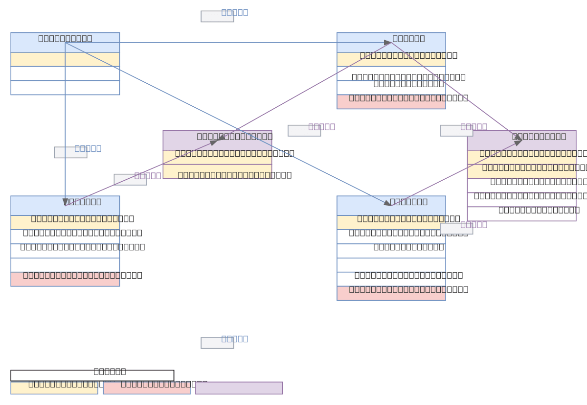
University Database ER Diagram models a complete academic institution schema with DEPARTMENT, TEACHER, COURSE, and STUDENT entities connected through normalized relationships. Data flows from DEPARTMENT to TEACHER, COURSE, and STUDENT; TEACHER and COURSE connect via TEACHER_COURSE junction table to resolve many-to-many assignments; STUDENT and COURSE link through ENROLLMENT to track semester grades and registration dates. This schema enforces referential integrity and eliminates data redundancy, critical for managing complex academic workflows, course scheduling, and student records at scale. Fork and customize this diagram on Diagrams.so to adapt it for your institution's specific requirements, then export as .drawio or .png for documentation and database design reviews.
People also ask
What does a normalized university database ER diagram look like with departments, teachers, courses, and student enrollments?
This ER diagram shows a normalized university schema where DEPARTMENT is the parent entity for TEACHER, COURSE, and STUDENT; TEACHER_COURSE is a junction table resolving the many-to-many relationship between TEACHER and COURSE; ENROLLMENT links STUDENT to COURSE with semester and grade tracking. The design uses primary and foreign keys to enforce referential integrity and eliminate redundancy.
- Domain:
- Data Engineering
- Audience:
- Database designers and university IT administrators building relational schemas
Generated by Diagrams.so — AI architecture diagram generator with native Draw.io output. Fork this diagram, remix it, or download as .drawio, PNG, or SVG.