Wireless Network Architecture - Full Redundancy
About This Architecture
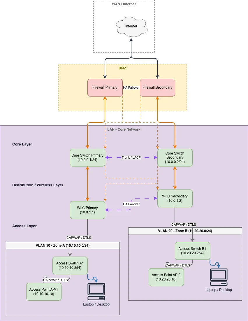
Enterprise wireless network with dual firewalls, redundant core switches, and distributed wireless LAN controllers ensuring zero single points of failure. Internet traffic routes through primary and secondary firewalls to redundant core switches (10.0.0.1/24 and 10.0.0.2/24), which interconnect and feed dual WLCs (10.0.1.1 and 10.0.1.2) managing access points across multiple VLANs. Each access layer zone—VLAN 10 (Zone A) and VLAN 20 (Zone B)—connects through dedicated access switches to APs and endpoints, with cross-layer failover paths ensuring continuous connectivity. This architecture eliminates bottlenecks and provides automatic failover if any single component fails, critical for mission-critical wireless deployments. Fork and customize this diagram on Diagrams.so to match your IP addressing scheme, add additional zones, or integrate with your specific WLC platform.
People also ask
How do you design a wireless network with no single point of failure using redundant firewalls, core switches, and WLCs?
This diagram shows a fully redundant wireless architecture where dual firewalls and core switches (10.0.0.1/24 and 10.0.0.2/24) provide failover at the perimeter and core, while redundant WLCs (10.0.1.1 and 10.0.1.2) manage access points across multiple VLANs with cross-layer connectivity ensuring continuous service.
- Domain:
- Networking
- Audience:
- Network architects designing enterprise wireless infrastructure with high availability
Generated by Diagrams.so — AI architecture diagram generator with native Draw.io output. Fork this diagram, remix it, or download as .drawio, PNG, or SVG.