Synchronous FSM - D Flip-Flop Control Logic
About This Architecture
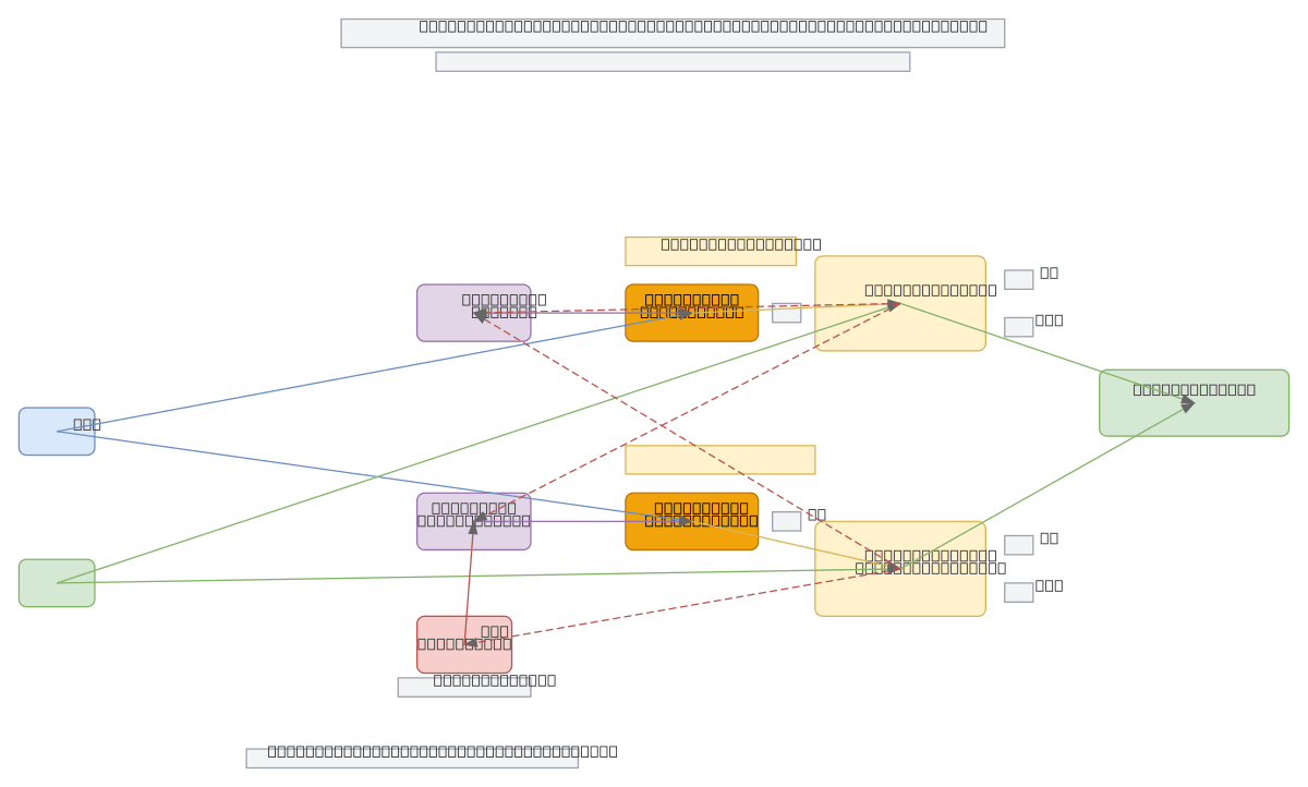
Synchronous FSM using D flip-flops with combinational logic gates implements a four-state controller driven by button input and clock signal. Q1 and Q0 outputs from dual D flip-flops feed back through OR and AND gates to generate next-state inputs D1 and D0, with an inverter providing NOT(Q0) for state transition logic. The circuit transitions between states 00, 01, 10, and 11 based on button press conditions evaluated at each clock edge. Fork this diagram to customize state transitions, modify gate logic, or adapt the FSM for your specific control application. This topology demonstrates synchronous design principles: all state changes occur on clock edges, eliminating race conditions and ensuring predictable behavior.
People also ask
How do D flip-flops and logic gates implement a synchronous finite state machine?
This diagram shows a synchronous FSM where D flip-flops store state bits Q1 and Q0, while OR and AND gates compute next-state inputs D1 and D0 based on current state and button input. The clock signal synchronizes all state transitions, ensuring predictable behavior and eliminating race conditions in the control logic.
- Domain:
- Electrical Engineering
- Audience:
- Digital logic designers and electrical engineers implementing synchronous finite state machines
Generated by Diagrams.so — AI architecture diagram generator with native Draw.io output. Fork this diagram, remix it, or download as .drawio, PNG, or SVG.