Redundant Wireless Network -
About This Architecture
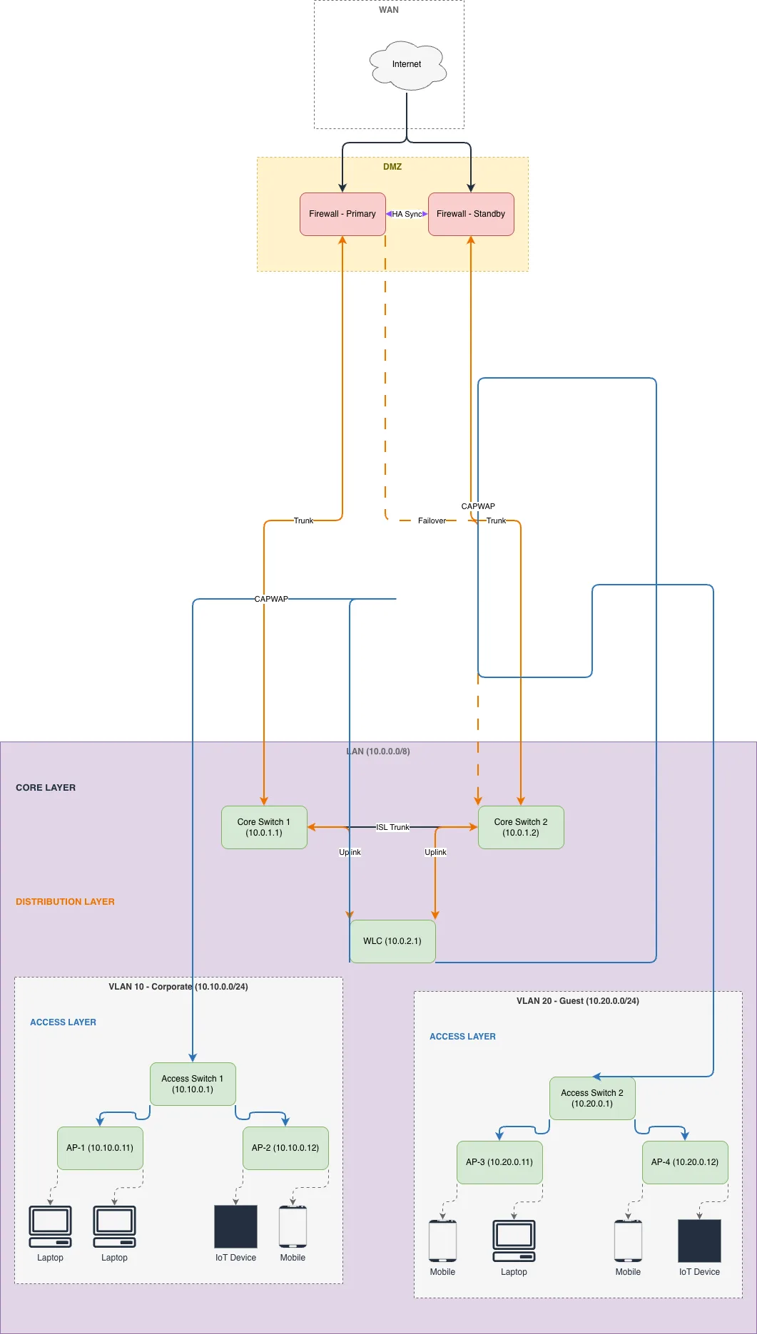
Redundant wireless network with dual firewall failover, core layer switch redundancy, and segregated VLANs for corporate and guest traffic. Internet connects through Primary and Standby firewalls that feed dual Core Switches (10.0.1.1 and 10.0.1.2), which converge at a centralized WLC managing four access points across two access layers. VLAN 10 (Corporate, 10.10.0.0/24) and VLAN 20 (Guest, 10.20.0.0/24) isolate traffic while supporting laptops, mobile devices, and IoT endpoints. This three-tier design eliminates single points of failure at the perimeter and core, ensuring continuous wireless service during maintenance or outages. Fork this diagram on Diagrams.so to customize IP ranges, add additional VLANs, or integrate with your security policies. The architecture demonstrates best practices for enterprise-grade wireless deployments requiring 99.9% uptime.
People also ask
How do you design a redundant wireless network with firewall failover and VLAN segmentation?
This diagram shows a three-tier redundant wireless network where dual firewalls (Primary and Standby) provide perimeter failover, dual Core Switches (10.0.1.1 and 10.0.1.2) eliminate core bottlenecks, and a centralized WLC manages four access points across VLAN 10 (Corporate) and VLAN 20 (Guest). This architecture ensures continuous wireless service and traffic isolation during component failures.
- Domain:
- Networking
- Audience:
- Network architects designing enterprise wireless infrastructure with high availability
Generated by Diagrams.so — AI architecture diagram generator with native Draw.io output. Fork this diagram, remix it, or download as .drawio, PNG, or SVG.