KNX BMS Control System Architecture
About This Architecture
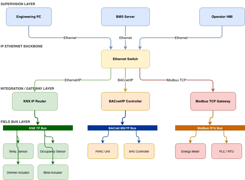
Multi-protocol building management system integrating KNX, BACnet, and Modbus devices through a centralized IP Ethernet backbone and gateway layer. The supervision layer—comprising Engineering PC, BMS Server, and Operator HMI—communicates via Ethernet Switch to protocol-specific gateways (KNX IP Router, BACnet/IP Controller, Modbus TCP Gateway) that bridge to field buses. Each field bus layer manages sensors, actuators, and controllers: KNX TP Bus handles lighting and occupancy control, BACnet MS/TP Bus manages HVAC and AHU systems, and Modbus RTU Bus monitors energy meters and RTU devices. This architecture enables interoperability across legacy and modern building systems while maintaining protocol-native performance at the device level. Fork and customize this diagram on Diagrams.so to design your own multi-vendor BMS topology, then export as .drawio, SVG, or PNG for documentation and stakeholder review.
People also ask
How do you integrate KNX, BACnet, and Modbus devices in a single building management system?
Use a centralized IP Ethernet backbone with protocol-specific gateways: KNX IP Router bridges KNX TP Bus devices (sensors, actuators), BACnet/IP Controller manages BACnet MS/TP HVAC systems, and Modbus TCP Gateway connects Modbus RTU energy meters and PLCs. A supervision layer (BMS Server, Operator HMI, Engineering PC) communicates via Ethernet Switch to all gateways, enabling unified monitoring a
- Domain:
- Building Automation
- Audience:
- Building automation engineers designing multi-protocol BMS systems
Generated by Diagrams.so — AI architecture diagram generator with native Draw.io output. Fork this diagram, remix it, or download as .drawio, PNG, or SVG.