Impulse Control - 5/2 Bi-Stable and 3/2 Valves for
About This Architecture
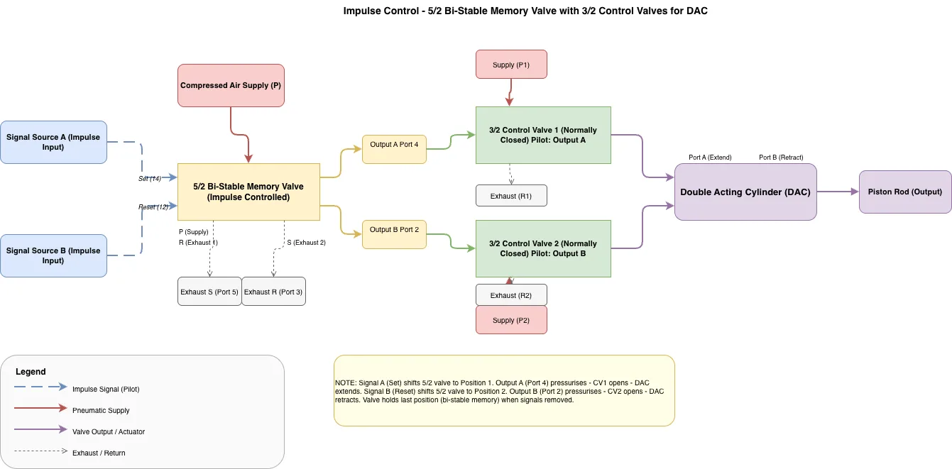
Impulse control circuit using a 5/2 bi-stable memory valve with dual 3/2 pilot-operated control valves to manage a double-acting cylinder. Compressed air supply feeds the bi-stable valve, which receives impulse signals from two sources (Set and Reset) and outputs pilot pressures to the 3/2 control valves. The 3/2 valves (normally closed) are pilot-actuated by outputs from the bi-stable memory valve, directing supply pressure to cylinder ports A and B for extend and retract motion. This architecture demonstrates latching logic without electrical controls, ideal for hazardous environments or pneumatic-only automation. Fork this diagram on Diagrams.so to customize valve sizes, add flow controls, or integrate additional actuators. The bi-stable memory function ensures the cylinder holds position after impulse removal, reducing energy consumption.
People also ask
How do you control a double-acting cylinder using impulse signals and a bi-stable memory valve without electrical controls?
This diagram shows a pneumatic impulse control circuit where a 5/2 bi-stable memory valve receives Set and Reset impulse signals, then outputs pilot pressure to two 3/2 normally-closed control valves that direct supply to the cylinder's extend (Port A) and retract (Port B) ports. The bi-stable valve latches the output state after each impulse, holding the cylinder position without continuous pilot
- Domain:
- Mechanical Engineering
- Audience:
- pneumatic systems engineers designing impulse-controlled actuator circuits
Generated by Diagrams.so — AI architecture diagram generator with native Draw.io output. Fork this diagram, remix it, or download as .drawio, PNG, or SVG.