I2S Transmitter RTL Datapath and Controller
About This Architecture
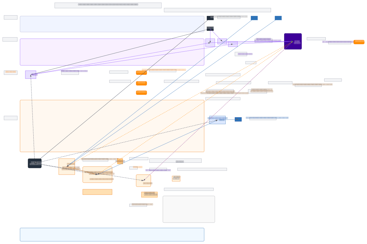
I2S transmitter RTL datapath and controller implements a complete digital audio serialization pipeline for FPGA designs. The architecture combines edge detection and finite state machine control to synchronize left and right audio channels with BCLK and LRCLK clock domains, routing 24-bit stereo samples through a 32-bit shift register for MSB-first serial output. The datapath uses a 2:1 multiplexer to select between left and right audio data based on LRCLK rising edge detection, padding samples to 32 bits and shifting out one bit per BCLK falling edge. This design demonstrates best practices for audio codec integration: proper clock domain handling, deterministic bit counting, and clean separation of control logic from datapath operations. Fork this diagram to customize bit widths, add parity or CRC protection, or adapt for different audio standards like S/PDIF or TDM. The modular FSM and shift register architecture makes it ideal for teaching RTL design patterns or as a foundation for production audio interfaces.
People also ask
How do you implement an I2S transmitter in RTL with proper clock synchronization and stereo channel multiplexing?
This diagram shows a complete I2S transmitter RTL design using an FSM to detect LRCLK edges, a 2:1 multiplexer to select left or right audio data, and a 32-bit shift register clocked by BCLK falling edges to serialize 24-bit audio samples MSB-first. The bit counter and FSM coordinate loading and shifting operations, ensuring deterministic timing and clean handoffs between control and datapath logi
- Domain:
- Electrical Engineering
- Audience:
- Digital design engineers and FPGA developers implementing I2S audio interfaces
Generated by Diagrams.so — AI architecture diagram generator with native Draw.io output. Fork this diagram, remix it, or download as .drawio, PNG, or SVG.