ESP32 Smart Irrigation System Block Diagram
About This Architecture
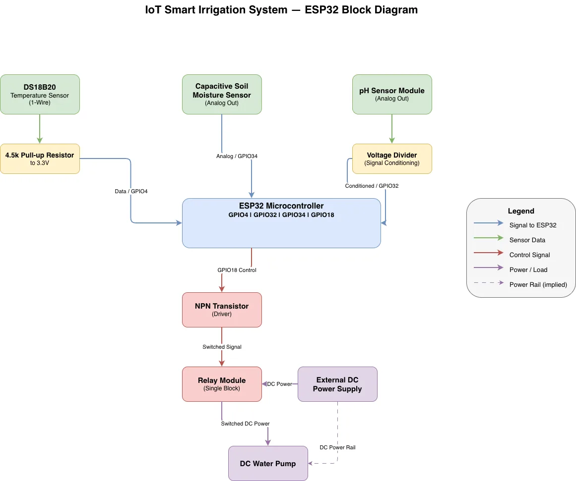
ESP32-based smart irrigation system integrating temperature, soil moisture, and pH sensors for automated watering control. The ESP32 microcontroller reads analog and digital sensor inputs via GPIO pins, processes environmental data, and drives a relay-controlled DC water pump through an NPN transistor driver stage. This architecture demonstrates sensor signal conditioning, power isolation, and closed-loop irrigation automation for precision agriculture and landscape management. Fork this diagram on Diagrams.so to customize GPIO assignments, add WiFi connectivity, or integrate cloud logging for remote monitoring. The voltage divider on the pH sensor exemplifies proper analog signal scaling for the ESP32's 3.3V ADC range.
People also ask
How do I design an ESP32 smart irrigation system with multiple sensors and automated water pump control?
This diagram shows how to connect temperature (DS18B20), soil moisture, and pH sensors to ESP32 GPIO pins, condition analog signals with a voltage divider, and drive a water pump relay through an NPN transistor. The architecture isolates the high-current pump load from the microcontroller using a relay module powered by an external DC supply.
- Domain:
- Electrical Engineering
- Audience:
- embedded systems engineers and IoT developers building smart irrigation solutions with ESP32
Generated by Diagrams.so — AI architecture diagram generator with native Draw.io output. Fork this diagram, remix it, or download as .drawio, PNG, or SVG.