Campus Network - 2-Floor Computer Laboratory
About This Architecture
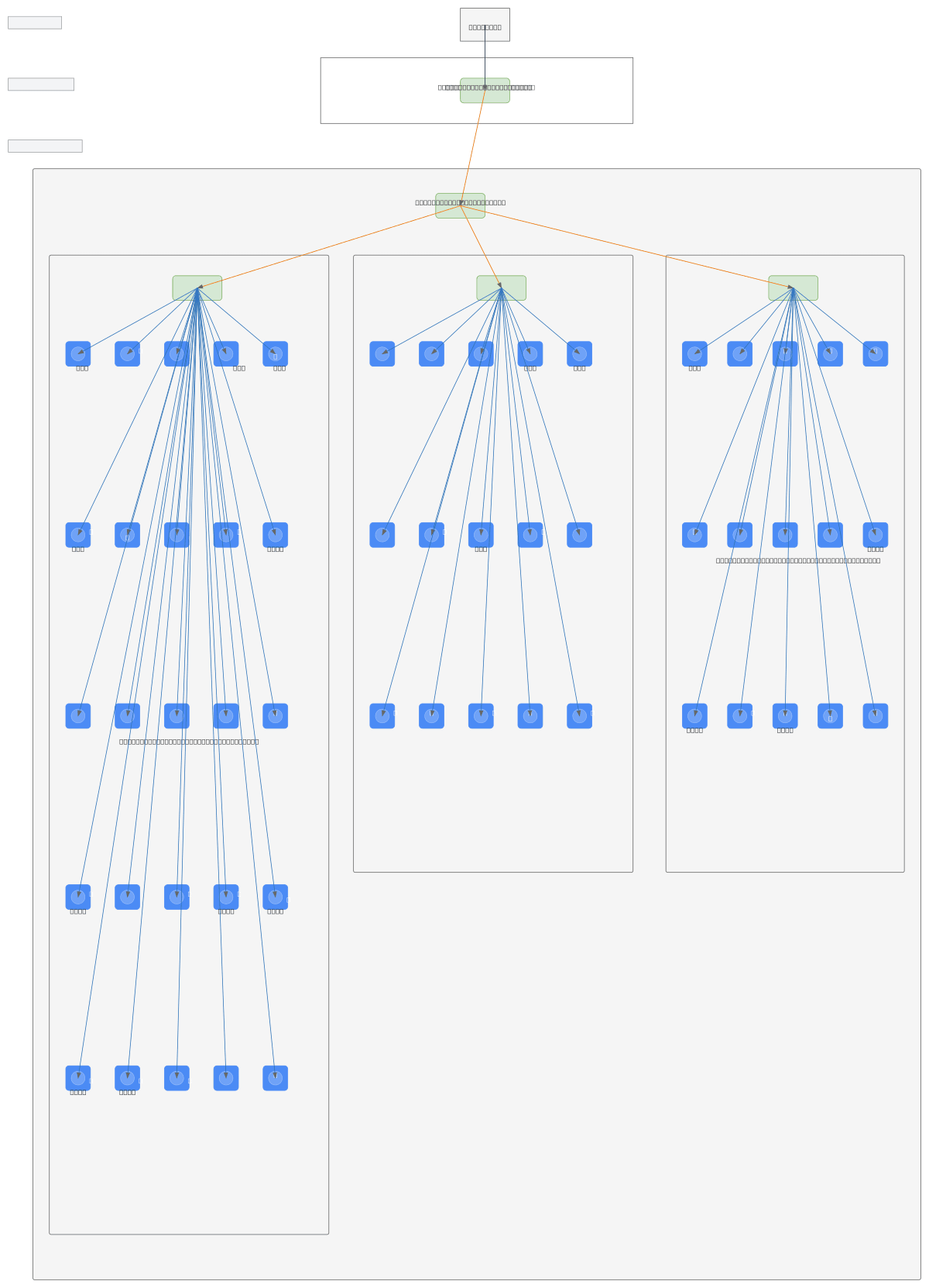
Two-tier campus network connecting a 2nd Floor Core Layer and 1st Floor Computer Laboratory across 55 PCs organized into three distinct segments. Internet traffic flows through the Main Router on the 2nd Floor, then down to the Lab Router on the 1st Floor, which distributes connectivity to Hub 1 (25 PCs), Hub 2 (15 PCs), and Router 2 (15 PCs). This hierarchical topology isolates lab traffic by section while maintaining centralized gateway control, reducing broadcast domains and improving network stability. Network administrators can fork this diagram to customize VLAN assignments, add redundancy, or scale additional lab sections. The hub-based architecture is ideal for educational environments where cost-effective connectivity matters more than enterprise-grade switching.
People also ask
How should I design a network topology for a two-floor computer laboratory with multiple PC segments?
This diagram shows a hierarchical campus network with a Main Router on the 2nd Floor Core Layer feeding a Lab Router on the 1st Floor, which then distributes to three segments: Hub 1 (25 PCs), Hub 2 (15 PCs), and Router 2 (15 PCs). This segmentation reduces broadcast domains, improves stability, and simplifies management of 55 lab computers across floors.
- Domain:
- Networking
- Audience:
- Network administrators managing campus lab infrastructure
Generated by Diagrams.so — AI architecture diagram generator with native Draw.io output. Fork this diagram, remix it, or download as .drawio, PNG, or SVG.