AWS Multi-Region Disaster Recovery Architecture
About This Architecture
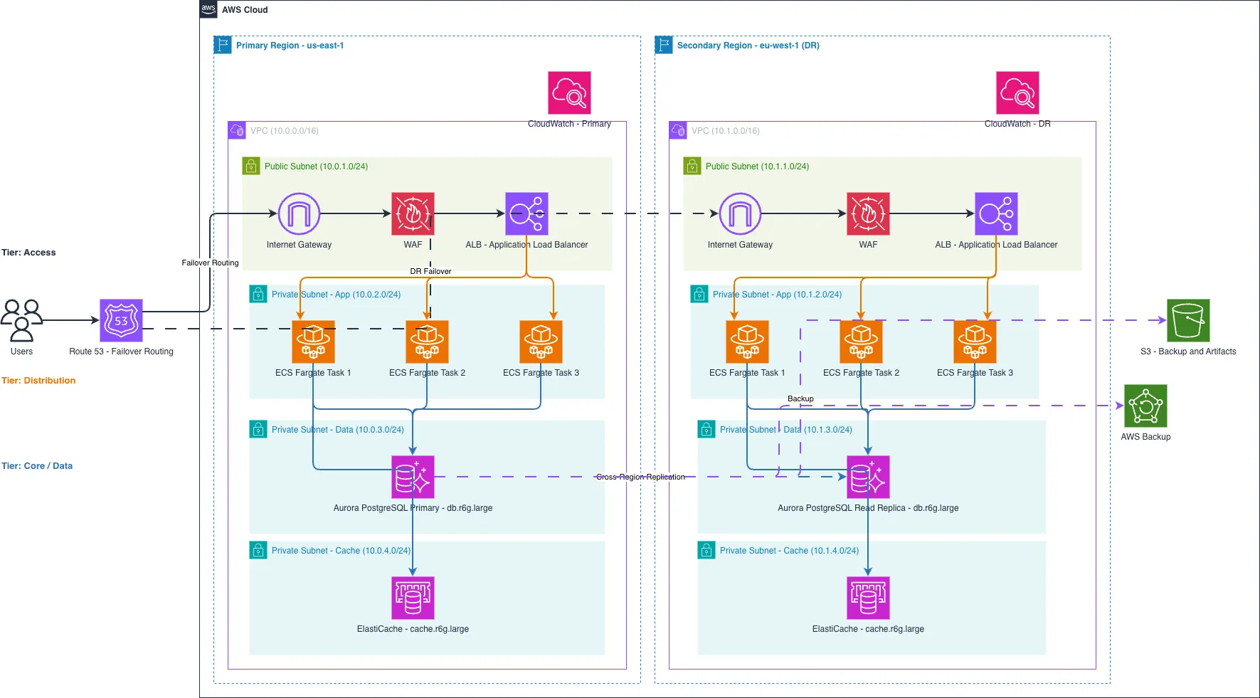
Multi-region active-passive disaster recovery architecture spanning AWS us-east-1 and eu-west-1 with Route 53 failover routing, ECS Fargate compute, and Aurora PostgreSQL replication. Traffic flows through Route 53 to the primary region's Internet Gateway, WAF, and Application Load Balancer, distributing across three ECS Fargate tasks that query Aurora PostgreSQL Primary and ElastiCache. The secondary region mirrors this topology with an Aurora PostgreSQL Read Replica and standby ECS Fargate cluster, synchronized via cross-region replication and AWS Backup. This architecture minimizes RTO and RPO by maintaining hot standby infrastructure, automated failover via Route 53 health checks, and continuous database synchronization. Fork and customize this diagram on Diagrams.so to adjust regions, instance types, or add additional tiers like DynamoDB or Kinesis. The three-tier design (Access via WAF/ALB, Distribution via ECS, Core/Data via Aurora and ElastiCache) ensures separation of concerns and independent scaling.
People also ask
How do I design a multi-region disaster recovery architecture on AWS with automatic failover and minimal downtime?
This diagram shows an active-passive DR setup using Route 53 failover routing to direct traffic between us-east-1 (primary) and eu-west-1 (secondary) regions. ECS Fargate tasks in each region connect to Aurora PostgreSQL Primary in the primary region and a Read Replica in the secondary region, with AWS Backup and cross-region replication ensuring data consistency and recovery capability.
- Domain:
- Cloud Aws
- Audience:
- AWS solutions architects designing multi-region disaster recovery strategies
Generated by Diagrams.so — AI architecture diagram generator with native Draw.io output. Fork this diagram, remix it, or download as .drawio, PNG, or SVG.